
Introduction: Why Do Water Purifiers Need Conductivity and TDS Signals?
In water purifiers, the most common number consumers see is TDS. But for R&D personnel, TDS is not an independent sensor; it is a result derived from conductivity conversion and temperature correction. Conductivity reflects the total concentration of conductive ions in water, while TDS is approximated as the mass concentration of total dissolved solids. The value of these signals lies not in providing a complete water quality safety conclusion, but in offering a low-cost, continuous, embeddable "trend quantity" and "abnormality quantity" for display, filter management, and after-sales judgment.
It must be clarified upfront: conductivity or TDS can only characterize the total amount of ionic dissolved substances in water; it cannot identify specific ions, organics, microorganisms, colloids, or disinfection byproducts. Therefore, it is a field screening and trend monitoring tool and cannot replace laboratory hygiene safety or pollutant analysis. Water purifier brands must communicate this boundary in user interfaces and after-sales scripts.
1. Four Key Application Scenarios
1. Water Quality Display: From "Is It Drinkable" to "How Much It Changes"
For users, the TDS number is the most intuitive "water purification effect" feedback. But for engineers, the more valuable aspect is relative change: the difference between raw water TDS and purified water TDS, and the trend of the same water source over time. Conductivity/TDS sensors can provide this trend.
Typical usage: place a conductivity/TDS probe at both the inlet and outlet of the water purifier, and calculate the desalination rate or removal rate by the difference. When the difference drops significantly, it often indicates membrane or filter performance degradation; when the outlet TDS rises abnormally, it may indicate seal failure, water cross-flow, or sensor fouling.
2. Filter Management: From Time Counting to State Estimation
Traditional filter life is based on flow or time accumulation, but raw water quality varies greatly by region, and fixed cycles can lead to premature replacement or running beyond failure. Conductivity/TDS signals can serve as one input for filter state estimation.
For example, for reverse osmosis or nanofiltration membranes, the ratio of outlet TDS to inlet TDS can reflect the desalination efficiency. When this ratio consistently exceeds a set threshold, a replacement reminder should be triggered even if the rated time has not been reached. For activated carbon filters, conductivity changes are usually insensitive, so it cannot be the sole basis for life; in this case, signals such as flow, pressure difference, or turbidity need to be combined.
3. After-Sales Diagnostics: Quickly Determine Whether the "Water" or the "Machine" is at Fault
In after-sales scenarios, users often report "high TDS in the water purifier." Without conductivity/TDS data, service personnel must visit to disassemble and inspect. With real-time or recorded data, remote judgments can be made: whether raw water TDS itself is high, whether the inlet-outlet difference is normal, and whether the sensor is drifting or fouled. This can significantly reduce ineffective visits and misdiagnosis of spare parts.
Therefore, when designing the sensor data chain, it is recommended to store the original TDS/conductivity values, temperature values, and status flags from recent operating cycles on the device side and upload them via IoT to the after-sales platform.
4. User Education: Understanding the Number Without Misinterpreting It
Explain to users that TDS is not a safety indicator. Design the UI with trend bars, differences, etc., rather than a single number, to help users develop correct understanding and reduce false complaints. For example, when raw water TDS is very high, as long as the output TDS is significantly lower than the raw water, it should be displayed as "filtration effective" rather than compared to an absolute safe value. This avoids panic when users see that TDS is not zero due to conductivity from natural minerals in drinking water.
2. Technical Basis: Measurement Chain for Conductivity and TDS
1. Conversion from Conductivity to TDS
Conductivity (unit µS/cm or mS/cm) is the reciprocal of resistivity, obtained by applying an AC signal to two electrodes and measuring the current. TDS (unit ppm or mg/L) is usually obtained by multiplying conductivity by an empirical coefficient, commonly between 0.5 and 0.7, depending on the ionic composition of the water. The coefficient differs for different water sources (e.g., groundwater, surface water, tap water), so the product should allow adjustment or segmented settings during calibration.
2. Temperature Compensation
Ionic mobility increases with temperature, so conductivity measurements must be temperature-corrected. Typically, measurements are normalized to a 25 °C reference. Both BA111 and BA121 support automatic temperature correction, reducing the burden of external compensation circuits and software.
3. Probe Polarization and Bipolar Drive
DC excitation causes polarization on the electrode surfaces, leading to measurement errors and electrode aging. Using bipolar (alternating positive and negative) drive can effectively reduce polarization effects. Both BA111 and BA121 have built-in bipolar probe drive, which reduces external circuitry and long-term drift in the design.
4. Probe Selection and Installation Considerations
The probe cell constant (e.g., K=0.1, 1.0, 10) should match the target range. Low conductivity water samples use low cell constant probes, and high conductivity water samples use high cell constant probes. During installation, avoid bubbles accumulating on the electrode surface; the probe should be in stable water flow and away from electromagnetic interference from pumps and switching power supplies.
3. Selection Method: BA111 or BA121?
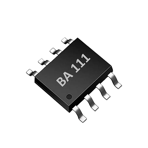
AtomBit offers two interface ASICs directly for water purifier applications: BA111 (single-channel TDS sensor interface ASIC) and BA121 (single-channel conductivity sensor interface ASIC). Both are highly integrated solutions suitable for space-constrained water purifiers or water appliances.
| Model | Main Output | Measurement Range | Key Features |
|---|---|---|---|
| BA111 | TDS (0–3000 ppm) and water temperature | 0–3000 ppm | TDS temperature correction; single channel; bipolar drive; minimal external components |
| BA121 | Conductivity and water temperature | Depends on conductivity range calibration | Patented conductivity conversion algorithm; automatic temperature correction; single channel; bipolar drive |
Selection Suggestions:
- If the product needs to directly display TDS (most household water purifiers) and is mainly concerned with the 0–3000 ppm range, prioritize BA111 to reduce MCU-side conversion and temperature compensation development.
- If the product needs more flexible conductivity output, for example for industrial or commercial equipment, requires custom TDS conversion coefficients, or needs to connect to different range probes, choose BA121.
- If the same device needs to monitor both inlet and outlet water simultaneously, you can use two BA111 (each single channel) or one BA121 with external multiplexing, but the impact of channel switching on measurement cycle and calibration must be evaluated.
Both are controlled via UART, making MCU reading and calibration easy; minimal external components make them suitable for SMD and compact designs.
4. Integration Implementation Steps
The following is a typical design and verification process for a water purifier conductivity/TDS sensing chain:
1. Probe Selection and Installation Location
Select a conductivity probe that matches the ASIC electrical parameters (cell constant, withstand voltage, material). The installation location should avoid bubble accumulation, stagnant water flow, and strong electromagnetic interference. The inlet probe is recommended to be installed after pre-treatment and before the core filter; the outlet probe installation before or after post-carbon should be determined based on specific goals (if measuring desalination rate, measure before and after the core membrane).
2. Circuit Connection and Communication
Connect the probe, power, and UART pins according to the BA111/BA121 datasheet. Note that analog and digital grounds should be connected at a single point, and the drive lines should be as short as possible and away from switching power supplies. After power-up, send calibration and read commands via UART. The chip internally completes signal conditioning, temperature compensation, and unit conversion; the MCU only needs to parse the returned data.
3. Calibration and Temperature Verification
Use standard conductivity solutions (e.g., 84 µS/cm, 1413 µS/cm, 12.88 mS/cm as appropriate) for two-point or multi-point calibration. Also record the water temperature to verify the accuracy of temperature correction. Calibration data should be stored in the MCU or the ASIC's non-volatile area.
4. Threshold Setting and Algorithms
Based on the raw water distribution across different regions and filter characteristics, set the inlet-outlet TDS difference threshold, ratio threshold, and absolute upper limit threshold. It is recommended to set hysteresis and delay criteria to avoid false alarms from water flow fluctuations.
5. Whole-Machine Verification
- Use standard solutions to simulate different raw water qualities, verifying display error and repeatability.
- Run long-term with actual tap water to observe sensor drift and fouling.
- Compare with a laboratory conductivity meter to confirm consistency and deviation range.
5. Connection with Smart Terminals and OEM/ODM Integration
AtomBit, as the original manufacturer of water quality sensors and sensor interface ASICs, supports product integration from probes to interface chips and smart terminals. In smart water appliances and OEM integration applications (e.g., under-sink water purifiers, water purifiers with screens, IoT water purifiers), brands can customize probe harnesses, structural adaptations, interface protocols, and factory calibration. This allows the conductivity/TDS signals from BA111/BA121 to be incorporated into the whole-machine intelligent system, presenting trends to users via the display panel or app while transmitting status to the after-sales platform.
This integration approach reduces development difficulty for water purifier brands: the core signal chain is already completed inside the ASIC, so OEM teams only need to focus on structure, wiring, and user interface design, shortening the cycle from solution to mass production.
6. Limitations and Boundaries: Not a Water Quality Safety Conclusion
It must be clear to product and after-sales teams:
- Conductivity/TDS cannot detect bacteria, viruses, heavy metal ion types, pesticides, drug residues, microplastics, etc.
- Low TDS does not mean water is necessarily safe (for example, some pollutants hardly conduct electricity), and high TDS is not necessarily harmful (for example, natural mineral water).
- The signals given by the sensor are only for trend monitoring and abnormality alerts and cannot be used as a basis for compliance judgment. When hygiene safety or regulatory requirements are involved, qualified laboratory analysis methods must be adopted.
- Conductivity/TDS sensors may be affected by temperature compensation errors, electrode fouling, bubbles, water flow velocity, electromagnetic interference, etc., requiring regular maintenance and calibration.
7. Verification Approach: Division of Labor Between Field Screening and Laboratory Analysis
It is recommended to establish a three-level verification mechanism:
- Factory Verification: Use standard conductivity solutions to calibrate, ensuring the sensor's error within the range meets product specifications.
- On-site Trend Monitoring: The device collects inlet and outlet conductivity/TDS in real time for display, filter management, and remote diagnostics. This is screening and trend analysis.
- Laboratory Confirmation: When abnormalities or user complaints occur, collect water samples and send them to a qualified laboratory to test relevant indicators according to national or industry standards. Laboratory data is the final basis for judgment.
8. FAQ
Q1: Can conductivity and TDS sensors detect bacteria? No. Microorganisms such as bacteria and viruses do not directly contribute to conductivity, so TDS/conductivity cannot reflect microbial contamination. Microbiological safety of water requires professional microbiological testing.
Q2: Why do some water purifiers only have one TDS sensor? A single sensor is usually installed at the outlet to display purified water TDS and identify abnormalities. However, to determine the filter desalination rate, it is necessary to monitor the inlet TDS as well to calculate the difference or ratio. Therefore, high-end or remote-diagnosis products are recommended to have at least two measurement points.
Q3: Can BA111 and BA121 be directly replaced with each other? The interfaces and functions are similar, but the output quantities are different: BA111 outputs TDS directly, while BA121 outputs conductivity. If the original design used BA111 and expects direct reading, replacing with BA121 requires adding conversion logic on the MCU side. Selection should be based on product definition.
Q4: Will the sensor readings drift after long use? Possibly. Fouling, aging, or contamination of the electrode surface can cause drift. It is recommended to calibrate periodically with standard solutions and design automatic cleaning or reminder functions. The bipolar drive of BA111/BA121 reduces polarization and helps slow drift, but it cannot be completely eliminated.
Q5: Does low TDS mean the water purifier is qualified? No. Low TDS only indicates that ionic dissolved substances in the water are reduced; it does not mean all pollutants are removed. Whether a water purifier is qualified needs to be determined by whole-machine testing and hygiene license inspection according to relevant product standards.
Conclusion
Conductivity and TDS sensors in water purifiers play the role of a "trend inspector" rather than a "water quality referee." They provide key signals for water quality display, filter management, after-sales diagnostics, and user education in a low-cost, easy-to-integrate, and continuously operating manner. By properly selecting AtomBit's BA111 or BA121 interface ASICs, and combining them with reliable probes, calibration, and threshold design, water purifier brands can enhance product intelligence and user experience while keeping technical boundaries clear. However, all engineering decisions must remember: this is a field screening tool, not a substitute for laboratory analysis.