
Introduction: why filter life cannot rely on a single number
Filter life reminders for household water purifiers, water dispensers, coffee machines, smart cups and pet water fountains directly affect user experience and consumable repurchase. Many products simply count down by "days of use", but different regional water quality, different household water consumption and different seasonal temperatures can cause the actual remaining life of the same filter to vary greatly. A more reasonable approach is to have the device collect multiple types of sensor data and then have the brand's algorithm model issue reminders. It should be clarified here: the TDS/conductivity, flow, temperature, etc. in this article are device feedback and consumer-grade trend judgment, not laboratory water quality analysis; the final determination of filter life must be verified by the brand itself based on filter materials, target pollutants and complete-machine testing.
Available categories of sensor data
1. TDS/conductivity trends
TDS (total dissolved solids) and conductivity are the most common electrochemical parameters in water purifiers. For reverse osmosis (RO) membranes, a decline in salt rejection usually manifests as a rise in outlet TDS, so the ratio or difference trend between inlet TDS and outlet TDS can be used to help determine whether the RO membrane is nearing failure. Note that TDS cannot reflect non-conductive pollutants such as residual chlorine, organic matter and microorganisms; for filters such as PP cotton, activated carbon and ultrafiltration, TDS changes are often not obvious, so flow and time must be combined.
In engineering, conductivity/TDS measurement requires dedicated interface chips and probes. AtomBit's BA111 single-channel TDS sensor interface ASIC supports 0–3000 ppm TDS measurement, features TDS temperature compensation and bipolar drive, can reduce probe polarization, has simple peripheral circuitry and is suitable for integration into compact water purifier control boards. The BA121 conductivity sensor interface ASIC, according to AtomBit product information, uses a patented conductivity conversion algorithm and automatic temperature compensation, and can be used in applications that focus more on the raw conductivity signal. These two types of chips output TDS/conductivity and temperature as digital quantities; the life algorithm still needs to be completed by the main control MCU.
2. Flow and cumulative water consumption
Cumulative water throughput is a key variable in determining the life of mechanical filtration filters (PP cotton, activated carbon). Filter manufacturers usually provide a "rated total purified water volume", for example a reference value under specific water quality and flow rate. The device can accumulate water consumption through a flow meter or pulse water meter, and trigger a reminder when the cumulative flow approaches a certain proportion of the filter's rated capacity. If there is no hardware flow meter, it can also be estimated based on water pump running time and solenoid valve opening time, but accuracy will decrease.
In smart small appliances, combining flow data with TDS data can distinguish between "not used for a long time but calendar time has expired" and "short-term heavy water use causing premature saturation". For example, boiler inlet water in coffee machines and single-drink water volume in smart cups can both serve as flow inputs. The brand needs to choose the flow meter installation location according to the product structure: inlet side, outlet side or after the filter, and consider the impact of bubbles and water pressure fluctuations on metering.
3. Time and calendar life
Time is a fundamental dimension of filter life. Even if the device is not used for a long period, an activated carbon filter may still need replacement due to adsorption saturation, bacterial growth or material aging. A common practice is to set a maximum number of days of use, such as 6 months or 12 months, as a hard upper limit. However, time alone cannot determine life, because in low-frequency usage scenarios the filter may not have reached its capacity limit. A more reasonable approach is to have both time and cumulative flow/water consumption participate in the judgment: alert when either threshold is reached first, or follow weighting rules defined by the brand.
Time data is easy to obtain and requires no additional sensors, but the power-off retention of the RTC or main control clock must be considered, as well as restarting the timing after the user resets the filter reminder.
4. Temperature
Temperature plays two roles in filter life reminders: first, compensating conductivity/TDS measurements, and second, affecting filter performance and safety of use. Conductivity changes significantly with temperature, and the TDS reading of the same water sample may differ at different temperatures, so probes usually integrate an NTC thermistor. AtomBit's BA111 and BA121 both support automatic temperature correction; the BA234 multi-parameter sensor interface ASIC explicitly provides automatic NTC temperature compensation and outputs digital results via UART at 9600 bps. Temperature data can also be used to determine whether the device is in a high-temperature environment (such as the under-sink space in summer), avoiding false alarms or missed alarms. For water dispensers and coffee machines with heating functions, the temperature sensor can also assist in controlling the inlet water temperature.
5. User maintenance records
User maintenance records are not sensor data, but they are an important input for calibrating the life model. They include when the user replaced the filter, whether flushing was performed, whether the reminder was reset, and whether the device was powered off for a long time. These records can help brands revise their algorithms: if a large number of users continue using the filter for some time after the reminder with no obvious water quality deterioration, the reminder is too conservative; if users report scale or odor before the reminder appears, the reminder is too late. Maintenance records can be stored via APP, local EEPROM or the cloud, but privacy and offline scenarios need to be considered.
How to combine sensor data: from single parameters to multi-condition judgment
A single data source is prone to misjudgment. For example, looking only at outlet TDS may mistake fluctuations in inlet TDS for filter failure; looking only at cumulative flow may ignore the bacterial risk caused by long-term standing. A layered judgment approach is recommended:
| Data source | Filter types that can be judged | Main limitations |
|---|---|---|
| Outlet TDS/conductivity trend | RO membranes, ion exchange resins | Insensitive to activated carbon and PP cotton; affected by raw water fluctuations |
| Inlet-outlet TDS difference/desalination rate | RO membrane | Requires two probes or switching measurement |
| Cumulative flow/water consumption | PP cotton, activated carbon, ultrafiltration | Flow meter cost and accuracy; cannot reflect water quality changes |
| Calendar time | All filter elements (especially activated carbon) | Does not reflect actual usage intensity |
| Temperature | Measurement compensation, high-temperature monitoring | Cannot independently determine lifespan |
| Maintenance records | Model calibration | Depends on user behavior; may deviate |
Brands can start with two basic dimensions: time + cumulative flow. For RO machines, add TDS desalination rate trend; for activated carbon post-filters that improve taste, effluent TDS or conductivity can be added as an auxiliary, but mainly rely on flow and time. At the algorithm level, a simple threshold or state machine is sufficient for most products; if the product is connected and has sufficient data, upgrade to a usage-pattern-based prediction model. Either way, calibration must be done with actual water samples and aging tests.
Key points for integrating conductivity/TDS chips with probes
Chip selection
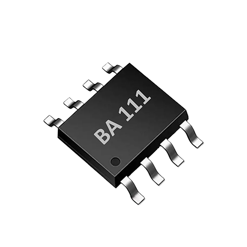
- If the product only needs a TDS digital value and the range is within 0–3000 ppm, BA111 offers high integration and simple peripherals, suitable for cost-sensitive water purifiers and smart cups.
- If the product focuses more on the raw conductivity signal, or requires a more flexible conductivity algorithm, BA121 provides single-channel conductivity detection and temperature measurement, automatic temperature correction, and bipolar drive.
- If the product requires two probes (for example, simultaneous measurement of inlet and outlet water, or separate placement of conductivity and temperature), BA234 provides a single-channel two-probe interface, automatic NTC temperature compensation, and UART digital output at 9600 bps, simplifying main-control communication.
These ASICs all use bipolar pulse excitation, which can reduce probe polarization, extend electrode life, and suit long-term online monitoring. However, parameters such as the specific excitation waveform, measurement cycle and power consumption must refer to the latest AtomBit datasheet, and the design should follow the recommended probe structure and harness length.
Probe and structural design
The probe is key to affecting mass-production consistency. The electrode material, area, spacing and surface treatment all affect the initial conductivity constant and long-term drift. Brands should require probe suppliers to provide initial consistency data and reserve calibration or compensation coefficients on the device side. Harness length and routing affect capacitive reactance, especially under high-frequency excitation, and must match the chip reference design. Temperature compensation depends on the thermal contact between the NTC and the electrodes; the probe potting process must ensure NTC response speed.
Software integration
BA111/BA121/BA234 all output digital results via UART; the main control MCU can read TDS/conductivity and temperature by sending simple control commands. This avoids insufficient main-control ADC accuracy and the difficulty of analog front-end design. The software should include the following modules:
- Sensor initialization and self-test;
- Periodic reading (e.g., every 10 seconds or each time water is drawn);
- Temperature compensation check (completed automatically by the chip, but the status bit must be confirmed);
- Data filtering (moving average, outlier removal);
- Lifespan algorithm state machine or model inference;
- Display and reminder interfaces (LED, seven-segment display, buzzer, APP push).
Implementation steps: from prototype to mass production
- Define the filter lifespan determination logic: clarify which filter needs monitoring, the target pollutants, the replacement threshold, and the false-alarm rate acceptable to users.
- Build a prototype data acquisition platform: use the BA111/BA121/BA234 development board or reference design, connect the probe, and collect data from water samples at different temperatures (5℃, 25℃, 45℃) and different TDS levels (e.g., 50 ppm, 250 ppm, 1000 ppm), recording the deviation between chip output and actual values.
- Establishing the calibration matrix: Prepare standard solutions in the laboratory covering the water quality range in which the product will be used; test the response of the flow meter and conductivity probe at different flow rates.
- Whole-unit aging and lifetime simulation: Run continuously with spiked water samples, actual tap water, and water samples from different regions, and observe sensor drift, probe scaling, and flow meter error accumulation.
- Algorithm validation and threshold adjustment: Feed the collected data into the lifetime algorithm and compare against manually determined filter failure points. If a cumulative flow threshold is used, verify whether the trigger time is reasonable under different hardness, temperature, and water usage patterns.
- Production testing and consistency control: Add a TDS standard solution calibration station on the production line and sample-test probe consistency; perform UART communication tests and reference value verification on circuit boards after ASIC soldering.
Limitations and Boundaries
- TDS is not a universal indicator: TDS can only reflect dissolved conductive ions and cannot directly detect bacteria, viruses, residual chlorine, pesticides, microplastics, etc. Therefore, TDS data cannot replace microbiological or chemical safety testing.
- Impact of raw water fluctuations: If only an outlet probe is installed, when raw water TDS is high, outlet TDS will also rise, which may falsely report filter failure. It is recommended to simultaneously collect raw water or use difference and ratio judgments.
- Although temperature compensation is automatic, the response lags: When the NTC thermal time constant does not match the rate of water temperature change, compensation will have a brief error, and the software should avoid making immediate judgments during rapid temperature changes.
- Probe aging and contamination: After long-term use, the electrode surface may scale or adsorb organic matter, causing conductivity readings to drift. The probe needs to be calibrated or replaced periodically, or a certain range of drift must be accepted.
- Filter life models are not universally applicable: Different brands of filter cartridges have different materials, structures, and fill amounts; even with the same TDS/flow data, service life may differ. AtomBit chips provide reliable sensor data, but do not provide ready-made life determination formulas; brands must complete whole-unit validation themselves.
- Not laboratory analysis: The device feedback described in this article is consumer-grade trend judgment and does not meet statutory water quality testing requirements. If used for compliance or safety claims, it must be based on national standards and certified laboratory testing.
Suggested validation methods
- Conductivity/TDS measurement accuracy: Test with metrologically traceable conductivity standard solutions (such as 1413 µS/cm, 12.88 mS/cm) in a constant-temperature bath, compare with a reference instrument, and record error and repeatability.
- Temperature compensation effect: Immerse the probe in standard solutions at different temperatures and observe whether the chip output is stable; calculate whether the temperature coefficient is within the expected range.
- Long-term drift: Continuously immerse the probe in moderately hard tap water for 30 days, record the reading changes weekly, and determine whether software calibration is needed.
- Whole-unit testing: Simulate actual user usage (intermittent water dispensing, long standby periods), and record whether the filter life reminder trigger time matches the actual contamination level of the filter. If conditions permit, disassemble the filter to observe clogging and adsorption saturation.
- Production sampling inspection: Sample and inspect the TDS reading consistency of probes and ASIC boards for each batch, set upper and lower limits to intercept defective products.
FAQ
Q1: Can the TDS value directly represent filter life? No. TDS reflects the total amount of dissolved salts and has some indicative value for the desalination rate of RO membranes, but it is not sensitive to filters such as activated carbon and PP cotton. It is recommended to use TDS in combination with cumulative flow and time.
Q2: Can BA111/BA121/BA234 directly output the remaining filter life percentage? No. These chips are conductivity/TDS sensor interface ASICs and output digital values of TDS/conductivity and temperature. The life percentage needs to be calculated by the brand's main control MCU or cloud based on an algorithm model.
Q3: Is temperature compensation automatic? Yes. BA111 provides TDS temperature correction, BA121 provides automatic temperature correction, and BA234 provides automatic NTC temperature compensation. However, the compensation algorithm targets standard water samples, and deviations may still occur when water quality is complex.
Q4: How can the impact of probe consistency differences on mass production be reduced? Choose probe suppliers with stable electrode sheet materials and structures; add a standard solution calibration station on the production line; reserve calibration coefficients in the software; use factory calibration or paired calibration when necessary.
Q5: Must the filter life reminder be connected to the network? Not necessarily. A local MCU reading sensor data and running simple thresholds or a state machine can implement it. Networking can record more data, remotely update algorithms, and analyze user behavior, but it increases cost and privacy concerns.
Q6: Can optical sensors (such as UV254, TOC) replace TDS for determining filter life? They cannot simply replace it. Optical sensors can detect some organic matter or turbidity, but they are costly and respond differently to different pollutants. In household devices, they can be used as a supplementary data source, but calibration must be performed for the target filter and pollutants. The conductivity/TDS solution focused on in this article is more suitable for widespread adoption in terms of cost and integration.
Conclusion
The water purifier filter life reminder is not a single TDS or timing issue, but an engineering issue involving multi-source sensor data fusion and brand algorithm validation. AtomBit's BA111, BA121, and BA234 conductivity/TDS interface ASICs provide a highly integrated, temperature-compensated, and digital-output sensing foundation for smart water appliances, helping hardware teams reduce analog design workload and lower the risk of probe polarization. However, truly reliable filter life reminders still depend on the brand's in-depth understanding of filter materials, usage scenarios, and user expectations, as well as sufficient laboratory and field validation. The technical content of this article is for product design reference only and does not constitute water quality safety certification or regulatory advice.