
Why small-appliance prototyping often gets stuck on water-quality sensing
Water-quality functions in smart water appliances increasingly resemble “standard capabilities”: water purifiers need to show TDS removal trends, water dispensers need to prompt filter replacement, coffee machines need to control the softness/hardness of brewing water, smart cups need to feed back on impurities in drinking water, and pet water fountains need to remind users to clean. But once many projects reach the prototype stage, conductivity/TDS readings become unstable, are heavily affected by temperature, data drifts after the probe is installed, and calibration results cannot be reproduced, slowing down the overall product schedule.
The goal of rapid prototyping is not to skip validation, but to isolate uncertainties in “structure, hardware, water samples and algorithms” as early as possible. For household products, the positioning must first be clarified: at the prototype stage, the water-quality sensor module is mainly used for consumer-grade screening, device feedback and trend prompts, not for laboratory compliance testing. With this boundary in mind, the following six steps are laid out: probe, interface ASIC, temporary wiring harness, main control, sample log and preliminary calibration.
Prototyping path overview
- First fix the probe structure to avoid the effects of hydraulics and bubbles.
- Then evaluate the interface ASIC to decide peripheral complexity and the data interface.
- Use a temporary wiring harness to connect the measurement front end to the main control and reduce interference.
- Establish samples and logs, retaining raw data and device status.
- Perform preliminary calibration: conductivity first, then temperature compensation, then whole-device integration.
- Use constraint conditions for regression validation.
This path is not about pursuing industrial-grade bench accuracy, but about enabling the team to obtain reproducible engineering data within two-week-level iterations. AtomBit's BA121 and BA234 interface ASICs and the TFE-1-A1 planar ring electrode probe can serve as a rapid-selection combination for this path.
1. Probe: solve installation first, then discuss accuracy
TFE-1-A1 is a compact planar ring electrode assembly, suitable for direct embedding into products such as water purifiers, water dispensers, and coffee machines. It uses a planar ring electrode geometry, has a smooth and easy-to-clean surface, integrates temperature sensing, and supports an insert-molded structure. This means that during prototyping, there is no need to first develop complex stainless steel electrodes or glass electrodes; the measurement point can be placed into the flow channel or water tank relatively quickly.
From an engineering perspective, the following should be confirmed first:
- Whether the probe installation position is located in a flow dead zone. If bubbles remain on the planar electrode surface, readings will be noticeably low and recovery will be slow.
- Whether the probe window is far from heating tubes, pump bodies, or strong electromagnetic interference. Space inside small appliances is limited, and PTC heating or pump startup may couple interference through the wiring harness.
- Whether the structural material is compatible with the probe surface. Printing transparent parts with 3D for prototyping allows observation of bubbles, but note that printing materials may release trace substances that affect low-conductivity water samples; formal validation should use food-contact-grade materials or thorough rinsing.
- TFE-1-A1 integrates temperature sensing, which can reduce the wiring and mounting of an external NTC channel. If structural constraints require an external NTC, it should be installed close to the probe and avoided being left suspended.
At the prototype stage, it is recommended to first make a detachable flow-channel module: package the probe separately, connect it via an adapter board, and merge it into the appliance water path after the validation data is stable. Although this adds one round of structural debugging, it can avoid the common problem of suspecting the sensor first when the data is incorrect.
2. Interface ASIC: selection decision for BA121 and BA234
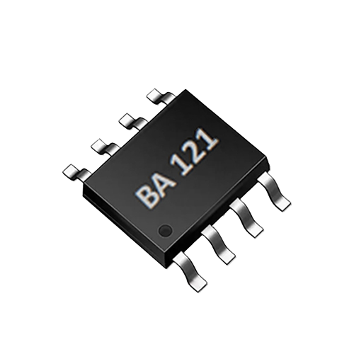
The value of the interface ASIC is to concentrate conductivity excitation, signal conditioning, and temperature processing into a small-size device, reducing analog debugging on the main control board of small appliances. AtomBit's two chips have slightly different positioning.
| Evaluation Dimension | BA121 | BA234 | Application in prototyping |
|---|---|---|---|
| Temperature handling | Automatic temperature correction | Automatic NTC temperature compensation | If the probe already integrates temperature, the harness can be simplified; for an external NTC, it is advisable to evaluate BA234 |
| Output and control | Needs to be evaluated together with the host controller resources | UART 9600 bps, simple control commands | BA234 interfaces with the MCU faster, and logs can be read directly |
| Peripheral complexity | Fewest external components | Single-channel dual-probe measurement | For space-constrained designs choose BA121; for rapid prototyping choose BA234 |
| Excitation method | Bipolar probe drive | Bipolar pulse excitation | Both reduce the risk of probe polarization and suit intermittent measurement in small appliances |
The advantage of BA121 is its minimal external component count, making it suitable for compact products with relatively strong host controller resources that want to keep the conductivity front end as close to the probe as possible. It features automatic temperature compensation and bipolar probe drive, and can be combined with TFE-1-A1 to form a small measurement node. BA234, by contrast, explicitly provides UART 9600 bps digital output and simple control commands, making it friendlier to embedded engineers: the host controller does not need to design additional high-precision analog acquisition, only to parse the digital output, so prototype joint debugging is faster.
If the team has not yet settled on a long-term platform, it is advisable to keep test points for both ASICs during the prototyping stage. First use BA234 to get the digital link, logs and overall device functions working, then evaluate whether BA121 is needed to further reduce BOM and area.
3. Temporary harness and main control board: keep variables confined to conductivity itself
The weak signals of a water-quality sensing module are easily disturbed by the harness and layout. Although a temporary harness is only for prototyping, a few rules still need to be followed:
- Keep excitation lines and sampling lines as short as possible, and avoid routing them parallel to pump and heater harnesses.
- If conditions allow, use twisted-pair or shielded cable, with the shield grounded at one end.
- Choose moisture-resistant connectors; detachable terminals can be used during prototyping, but crimp/solder-joint consistency and contact resistance must be verified before formal samples.
- The probe lead definitions must be fixed, especially the wire order after TFE-1-A1 temperature integration, to avoid abnormal compensation caused by reversed temperature pins.
For the main control board, if BA234 is used, UART 9600 bps can already provide digital quantities, so the MCU only needs to handle power supply, logic levels and command timing. Logs should record at least: raw conductivity-related output, temperature, compensated conductivity/TDS, displayed filtered value, timestamp, heater/pump status and operating mode. Only by retaining the raw values can you determine during an anomaly whether the problem is the probe, the ASIC or post-processing.
Small appliances usually do not require industrial isolation internally, but the large current return during motor and relay switching must be prevented from affecting the measurement ground. If necessary, add LC filtering at the ASIC power supply end, and record a baseline when no water is flowing and the motor is stopped.
4. Samples, logs and data stability
Prototype sampling cannot be limited to testing three cups of water. Standard samples and a sample set closer to actual conditions need to be established.
- Use traceable conductivity standard solutions and record the standard solution temperature. After opening, standard solutions should be stored sealed to avoid evaporation and contamination.
- Before measurement, rinse the probe thoroughly with pure water or deionized water and check whether the zero point is within the expected range.
- Remove bubbles: place the probe vertically or at an angle, gently tap the structure or run water briefly to release trapped air.
- The sample set should cover the product's typical operating conditions: raw water, purified water, pure water, mineral water/soft water, water after prolonged standing, etc. For household products, what matters is not full-range coverage but whether "differences users can perceive" can be reliably distinguished.
- The log records states such as standby, water flow, heating and low-water protection, making it easier to determine whether noise comes from the measurement chain or from system operating conditions.
When data is unstable, look for patterns in the log first: is it synchronized with heating? Is it synchronized with pump startup? Is it related to water flow rate? Does it drift after each power-up? This kind of time correlation is more valuable for engineering than absolute error.
5. Preliminary calibration: conductivity first, then temperature compensation, then the complete unit
Calibration for rapid prototyping does not need to achieve the multi-point curves of industrial inline instruments, but it must have a repeatable process.
Step 1: Conductivity calibration. Select two or three standard points that cover the product's typical water quality, and use a constant-temperature water bath or thermostat to keep the temperature stable. Record the relationship between the ASIC output and the conductivity of the standard solution. The low-conductivity range is strongly affected by contamination, so operate quickly to avoid the influence of CO₂ dissolution.
Step 2: Temperature compensation verification. Do not skip actual testing just because the chip is labeled "automatic temperature correction" or "automatic NTC compensation." Test at least two temperature points to confirm that the compensated conductivity/TDS output stays within the allowed range when temperature changes. Temperature compensation models are usually valid only within a certain range; household products may encounter room-temperature water, ice water and heated water.
Step 3: TDS display calibration. Conductivity is not equal to TDS, and the displayed value usually needs to be converted according to the product definition. At the product requirements stage, clarify whether the display is "conductivity-equivalent TDS" or a "specific water quality model," and record the conversion factor during calibration. Different water sources have different ion compositions, so TDS may differ at the same conductivity.
Step 4: Complete-unit integration. Install the module back into the water purifier, water dispenser or coffee machine, and run it using the actual water path and controller. Record scenarios such as startup flushing, water discharged from the filter, normal dispensing, heating, and dispensing after standing, and confirm that the displayed value does not jump abruptly due to bubbles, temperature or pump startup. For filter management functions, verify the trend logic of consumable life reminders using standard water samples, rather than looking only at a single-point TDS.
Limitations and applicable boundaries
- This method is intended for consumer-grade water quality screening, device feedback and trend indications, and does not replace laboratory analysis, hygiene and safety testing or regulatory compliance testing.
- The applicable boundaries of TFE-1-A1, BA121, and BA234 are subject to the product datasheet and actual sample verification; different structures, water temperatures, and conductivity ranges require re-evaluation.
- Module-level calibration cannot replace complete-device calibration. In a complete device, structural stress, sealing rings, housing materials, connectors, and wiring all affect long-term stability.
- Calibration coefficients obtained from rapid prototyping are suitable for engineering verification; for mass production, consistency verification on production structural parts and materials is still required.
Frequently Asked Questions (FAQ)
Q1: BA121 or BA234—which one should you choose? If you want minimal external components, have limited space, and the main controller has the relevant resources, BA121 can be evaluated first; if you want to obtain digital output quickly and reduce analog front-end debugging, the UART 9600 bps output of BA234 is more direct. It is recommended to first use BA234 to get the system running during the prototyping stage, and then evaluate whether to use BA121 to reduce the BOM.
Q2: Can TFE-1-A1 be soldered directly next to the mainboard? TFE-1-A1 is suitable for direct product integration, but it is not recommended to leave the probe suspended without structural support. The probe position needs to be fixed to ensure full contact between the measurement window and the water being measured; leads, soldering, and sealing should all meet the structural and electrical requirements of the complete device.
Q3: Can calibration be skipped for rapid prototyping? No. Skipping calibration may cause obvious errors, temperature drift, or batch inconsistency during prototype demonstrations. At minimum, two-point conductivity calibration and temperature compensation verification must be performed before proceeding to complete-device integration and debugging.
Q4: Why does the data suddenly jump during heating? Common causes include bubbles near the probe, delayed temperature compensation, or heater interference. First check the probe installation position and venting, then verify the temperature compensation response, and finally inspect the heater wiring harness and high-current loop.
Q5: Why does the TDS reading differ from that of a commercially available TDS pen? Different products may use different temperature compensation, conversion coefficients, and filtering strategies. First confirm the conductivity/TDS model defined by the product, then compare the raw conductivity values of the same sample at the same temperature, rather than directly comparing displayed values.
Q6: What should be noted for small-water-volume products such as pet water dispensers and smart water bottles? In small-water-volume products, the water sample changes quickly, the probe surface updates slowly, and the effects of bubbles and dead-water zones are more pronounced. Priority should be given to verifying the flow state in small-volume flow channels and avoiding long-term exposure of the probe to dry or semi-dry conditions.