
Why cables and connectors are the "hidden weak link" in smart hardware reliability
In the product development of smart water appliances, conductivity/TDS sensing solutions are usually seen as a simple combination of "chip + probe." But in actual mass production and user operation, the cables and connectors that link the probe to the mainboard often become high-incidence failure points. For devices such as water purifiers, water dispensers, coffee machines, smart water bottles and pet water dispensers, the probe may be installed on piping, water tanks or detachable parts, and the cable must withstand bending, stretching, vibration, temperature changes and moisture erosion; connectors face insertion/removal life, contact resistance, waterproof sealing and mis-insertion risks.
If these details are ignored, they may lead to reading drift, intermittent communication failure, temperature compensation errors, or even whole-device error shutdowns. This article, centered on AtomBit's probe products and smart water appliance integration practices, discusses how to control the reliability risks brought by cables and connectors from an engineering perspective.
Typical failure modes and engineering impact
1. Signal attenuation and noise coupling caused by cable length
For conductivity probes with analog output (such as NTC probes), cable length directly affects signal integrity. Conductivity measurement is essentially micro-current detection under AC or pulse excitation; cable resistance and distributed capacitance reduce the effective signal amplitude and may introduce mains-frequency or switching-power-supply noise. It is generally recommended to keep analog signal lines as short as possible and away from power lines and motor drive lines.
For digital output probes (such as the AtomBit 3/8-inch Digital Probe), although the signal is transmitted digitally, excessively long cables may still cause communication errors due to impedance mismatch or ground potential differences. During layout, the relationship between cable length, communication rate and pull-up resistance should be evaluated, and eye diagram or bit error rate testing should be performed at the prototype stage.
2. Conductor fatigue caused by bending and tensile force
Users may repeatedly bend the probe cable during use, especially in scenarios with detachable water tanks, movable doors or rotating parts. At bending points, the cable is prone to conductor breakage or insulation damage. Choosing multi-strand fine copper wire and a highly flexible jacket (such as silicone or TPE) can improve bending resistance. If necessary, add a strain relief structure at the cable outlet to prevent the cable from directly bearing tensile force.
3. Poor connector contact and oxidation
Connectors are another weak point. Frequent mating cycles or vibration can reduce contact pressure and increase contact resistance, thereby affecting power supply and signal quality. In humid environments, contacts may undergo electrochemical corrosion. It is recommended to use gold-plated contacts and connectors with locking mechanisms, and to specify a maximum number of mating cycles. For internal connections that are not accessible to users, consider soldering or crimping instead of plug-in connections.
4. Waterproof sealing failure
Condensation, splashing, or immersion risks often exist inside water appliances. If the probe connector is not waterproofed, water ingress can cause short circuits or corrosion. Common ingress protection ratings such as IP67 or IP68 apply to the connector itself, but the overall product design must also consider sealing at cable outlets, housing seams, and other locations. AtomBit probes use a solid molded structure with sealing at the cable outlet, but system integration still requires verification of the overall product's waterproofing.
5. Noise interference and ground loops
Conductivity measurement is sensitive to electromagnetic interference. Unshielded cables or poor shielding grounding can introduce noise and cause reading fluctuations. For analog signals, shielded twisted-pair cable is recommended, with the shield grounded at one end. For digital signals, ensure reliable ground connections and avoid multiple ground points that form loops. In PCB layout, analog and digital grounds should be properly separated.
6. Convenience and cost of repair and replacement
In after-sales repair, if the cable and probe are integrally molded and non-replaceable, a faulty probe may need to be replaced together with the cable, increasing costs. If the connector is properly designed, only the probe or the cable can be replaced. However, a pluggable design must consider on-site installation reliability to prevent user misconnection or poor contact. AtomBit's 3/8-inch quick-connect probe design facilitates installation and replacement, but the cable end still needs proper securing.
Selection and design approach
Cable selection key points
| Parameter | Recommendation | Reason |
|---|---|---|
| Conductor material | Stranded tinned copper | Corrosion-resistant, easy to weld |
| Insulation material | Food-grade PVC, TPE or silicone | Complies with drinking water contact requirements, good flexibility |
| Shielding | Shielded twisted pair for analog signals; for digital signals, determined by the environment | Suppress noise coupling |
| Jacket | Hydrolysis-resistant, high-temperature-resistant, low smoke zero halogen | Adapts to moisture and temperature changes |
| Wire gauge | Calculated based on current and voltage drop; usually 24~26 AWG is sufficient | Avoid excessive thickness that affects flexibility. |
Connector selection key points
- Contact resistance: as low as possible, preferably below 50 mΩ, with gold plating thickness ≥ 0.8 μm.
- Mating cycle life: select according to the product design life, generally ≥ 500 cycles.
- Waterproof rating: at least IP65; for humid areas or areas that may be submerged, use IP67/IP68.
- Locking method: with a latch or threaded lock to prevent loosening due to vibration.
- Foolproof design: use different pins or housings for different signals to prevent incorrect insertion.
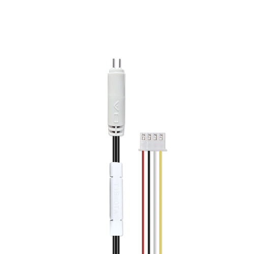
Layout and routing recommendations
- Keep cables away from heat-generating components (such as heating tubes and pump motors) to avoid high-temperature aging.
- Avoid sharp angles in the routing path; the bending radius should be greater than 5~10 times the cable diameter.
- Secure the cable with clamps or zip ties, but do not over-tighten—leave some slack for movement.
- Use single-ended grounding for the shield, with the ground point close to the mainboard ADC or processor.
- When evaluating EMC, include the probe and cable in the test and observe reading fluctuations.
Verification and mass-production control
Prototype verification stage
- Signal integrity test: measure conductivity accuracy at different cable lengths and compare attenuation and noise.
- Flex life test: simulate user use by repeatedly flexing the cable (e.g., 5000 times), then check conductor resistance and appearance.
- Pull test: apply the specified pull force at the connector to confirm it does not detach or make poor contact.
- Waterproof test: perform spray or immersion testing according to the IP rating, and measure insulation resistance and function.
- High/low temperature cycling: cycle from -10℃ to 60℃ and observe material deformation and connection reliability.
- EMC test: the complete unit passes the relevant standards while probe readings are monitored.
Key points for mass-production control
- Harness suppliers must provide material certificates and contact resistance test reports.
- Perform 100% inspection or sampling inspection of insertion/withdrawal force and appearance on key connectors.
- Develop cable layout work instructions and train workers to avoid damaging cables.
- Add a functional test station on the production line to simulate readings after actual installation.
AtomBit Products and Technical Support
AtomBit offers a variety of probe and interface solutions to help customers reduce cable and connector risks:
- 3/8-inch Digital Probe: digital signal output, strong anti-interference capability, and better adaptability to cable length; built-in high-precision temperature sensor reduces external temperature compensation cables; solid molded structure with reliable cable outlet sealing.
- 3/8-inch NTC Probe: integrated NTC temperature sensor simplifies cable routing; electrode materials available in titanium, gold, and platinum for corrosion resistance; food-contact-grade materials, suitable for drinking water equipment.
In OEM/ODM projects, AtomBit can customize cable length, connector type, and cable outlet direction according to customer structures, and provide layout recommendations and test support.
Limitations and Boundaries
- The content discussed in this article addresses the common low-conductivity, short-distance signal transmission scenarios of smart water appliances and is not applicable to industrial long-distance signal transmission.
- The reliability of probe cables is affected by the overall unit structure and usage environment, and must be verified in combination with specific products; it cannot be simply applied by analogy.
- Although the AtomBit probe offers a certain degree of water resistance, whole-device water resistance requires system-level design; the probe itself does not guarantee an IP rating for the complete device.
- The test parameters suggested in this article are empirical values and should be adjusted in practice according to product standards and company specifications.
FAQ (Frequently Asked Questions)
Q: What is the difference in cable length between analog probes and digital probes? A: Analog probe signals are weak; the longer the cable, the greater the attenuation and noise. It is recommended to keep the cable within 1 meters, and shielding is required. Digital probes output digital signals and can support longer cables, but signal integrity and power supply still need attention.
Q: Do connectors need to be waterproof? A: If the connector is located in an area that may contact water or high humidity, it needs to be waterproof. Otherwise, a standard connector can be used, but the impact of condensation must be evaluated.
Q: How should the cable shielding layer be grounded? A: For analog signals, the shielding layer should be grounded at a single point on the mainboard side to avoid ground loops. For digital signals, the shielding layer can be grounded at both ends or left floating as needed.
Q: How can cable faults be quickly identified? A: Measure the resistance across both ends of the cable. If the resistance is unstable or too high, the conductor may be broken or the contact may be poor. An oscilloscope can also be used to observe whether the signal waveform is abnormal.
Q: Can AtomBit probes be customized with cables and connectors? A: Yes. AtomBit supports OEM/ODM customization, including cable length, connector selection and cable exit method, which should be discussed at the early stage of the project.
Summary
Probe cables and connectors may seem simple, but they are a key link in the reliability of smart hardware. Through proper selection, layout and verification, the failure rate can be significantly reduced and the user experience improved. AtomBit's probe products and integration experience can help customers quickly implement reliable conductivity/TDS detection solutions.