
Introduction: the R&D risks behind the water-quality detection function
In smart small appliances such as water purifiers, water dispensers, coffee machines, smart water bottles and pet water fountains, water-quality detection has gradually changed from a differentiating selling point into a basic function users expect. But a seemingly simple "TDS display" or "filter life reminder" involves multiple engineering stages: analog front-end design, probe polarization suppression, temperature compensation, data calibration, mass-production consistency, after-sales data traceability and more. Negligence at any stage can lead to batch returns, repeated software iterations or runaway after-sales costs.
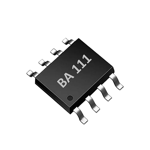
AtomBit has launched the BA111 single-channel TDS sensor interface ASIC and the BA121 conductivity sensor interface ASIC for smart water appliances and OEM integration. This article explains, from six aspects—IC maturity, interface clarity, sample verification, software collaboration, supply chain and after-sales traceability—how such dedicated interface ICs reduce R&D risk for smart small appliances, while clarifying which risks cannot be eliminated by the IC itself and must be verified by the system integrator.
1. IC maturity: absorbing the risk of "mass-producing" analog circuits in advance
Traditional water-quality detection solutions usually consist of op-amps, comparators, voltage-divider networks, temperature sensors and an MCU ADC. Design teams must not only handle small signals at the microsiemens level, but also solve problems such as drift caused by probe polarization, reading fluctuations caused by temperature changes, and batch differences caused by component tolerances. These risks are often not easily exposed at the prototype stage and only erupt in concentrated form during small-batch trial production.
BA111 and BA121 integrate the key parts of the above analog front end into a single ASIC, with fixed designs tailored to the typical requirements of smart water appliances:
- BA111 supports 0–3000 ppm TDS measurement, has built-in TDS temperature correction, performs single-channel measurement, uses bipolar drive to reduce probe polarization, and requires minimal external circuitry.
- BA121 is a single-channel conductivity detection ASIC that uses a patented conductivity conversion algorithm, performs automatic temperature correction, and likewise features bipolar probe drive and minimal external components.
"Maturity" here does not mean the IC vendor's self-proclamation; it means that once these functions are fixed in dedicated circuitry, the designer no longer needs to repeatedly build and debug discrete analog chains. The risk shifts from "building the circuit yourself" to "verifying how the IC performs in the target water matrix." The IC vendor has turned common issues such as bipolar drive and automatic temperature correction into deterministic behavior, so the R&D team can focus on structure, flow path, probe selection and whole-machine calibration.
But note: IC maturity solves the basic repeatability of the analog front end; it does not solve application-level issues such as probe materials, water sample contamination, bubble adhesion or long-term scaling. These still require whole-machine testing and verification.
2. Interface clarity: reducing hardware debugging and software integration risk
The R&D cycle for smart small appliances is often very short, with the hardware team and the embedded software team working in parallel. Unclear interface definitions cause both sides to repeatedly confirm timing, data formats and calibration commands, and can even lead to a situation where the hardware is complete but the software cannot correctly parse the data.
BA111/BA121 output digital values directly through a UART interface, so the MCU does not need a high-precision ADC, nor does the firmware need to implement complex temperature compensation algorithms. The UART control method makes data exchange simple:
- Hardware engineers only need to ensure that power, ground, UART TX/RX and probe connections are correct, with very few external components.
- Software engineers can read TDS/conductivity values and temperature values through standard serial commands without understanding the details of probe excitation.
- Bipolar drive is performed inside the IC, so the firmware does not need to alternately change probe polarity or synchronize sampling.
This clarity reduces cross-functional communication costs and also lowers design rework caused by inconsistent interface understanding. For OEM/ODM customers, AtomBit also provides customization of structure, wiring harness, interface and application calibration, making the IC, probe and whole-machine structure match better and avoiding later signal differences caused by harness length, connector type or probe mounting position.
Engineering advice: Confirm the UART baud rate, data frame format, command set and power-on initialization time at the project kickoff stage, and include UART communication in the whole-machine EMC test plan. A simple interface does not mean there is no timing risk—for example, the IC's stabilization time after power-on and whether serial data may be interrupted by interference from motors or pumps.
3. Sample verification: compressing prototype risk with standardized evaluation boards
Without good evaluation support, an IC-level solution forces the R&D team to draw boards, solder and debug on their own, which takes a long time and is error-prone. The "minimal external circuitry" feature of BA111/BA121 means evaluation boards can be built quickly, with verification focused on three levels: probe adaptation, flow-path effects and calibration curves.
The recommended verification process is as follows:
- Baseline function verification: Use standard conductivity solutions or known TDS solutions to confirm the IC's output linearity and repeatability at room temperature.
- Temperature effect verification: Gradually raise the test water sample from 5℃ to 60℃ (the actual product operating range may be narrower) and observe the change in readings after the chip's automatic temperature correction. During sudden temperature changes, check the reading stabilization time.
- Probe compatibility verification: Electrodes of different structures (pin-type, ring-type, plate-type) and different electrode spacings all affect the measurement range. It is necessary to confirm that the selected probe will not saturate or have insufficient resolution within the target water conductivity range.
- Complete-unit flow path verification: Assemble the probe into the actual water path and observe the effect of water flow rate, bubbles and dead-water zones on readings. In particular, test the first cup of water after startup, the first cup of water after long standby, and reading stability during continuous water dispensing.
- Long-term drift verification: Run continuously for several weeks and monitor the drift trend caused by scaling or contamination on the probe surface. The bipolar drive of BA111/BA121 can slow polarization, but cannot completely prevent electrode surface contamination.
Any anomaly found during the sample verification stage should be recorded as an "application-layer risk" rather than simply attributed to the chip. For example, reading jumps may be caused by pump start/stop interfering with the power supply, and overall high readings may be caused by the probe being installed close to a heater, resulting in locally excessive water temperature.
IV. Software collaboration: temperature compensation, display logic and filter management
The software functions of smart small appliances usually include: real-time TDS/conductivity display, filter life estimation, water quality anomaly alerts, historical data recording, etc. The chip provides temperature-corrected digital values, but how to turn these numbers into information understandable to users requires firmware and application-layer logic to work together.
4.1 Boundaries of temperature compensation
BA111 and BA121 have built-in automatic/patented temperature compensation, which solves the problem of water conductivity changing with temperature. However, compensation models are usually based on common water quality (such as aqueous solutions dominated by sodium salts). For coffee machines, tea machines and other appliances using special water sources (such as mineral water, purified water, or water with added flavorings), the compensated result may deviate from that of a laboratory conductivity meter. Therefore, firmware should not directly display raw compensated values that have not been calibrated for the complete unit; instead, offset calibration or segmented mapping should be performed according to the actual use scenario.
4.2 Display and threshold judgment
TDS display accuracy does not need to be pursued to laboratory level. Users care more about "whether the filter should be replaced" and "whether the water is normal." It is recommended that firmware use hysteresis comparison to avoid frequent jumps in readings near the threshold, which would cause a poor user experience. For example, filter replacement reminders can be based on a moving average over a period of time rather than a single reading.
4.3 Filter life management
Filter life cannot rely solely on a TDS desalination rate model. Water purifier filter life is affected by many factors such as water consumption, raw water quality, water passage time and flushing frequency. The TDS/conductivity data provided by the chip can serve as an auxiliary criterion, for example triggering a reminder when outlet water TDS remains continuously above a set threshold, but it is not recommended as the sole basis for replacement. A more reliable approach is to combine flow meter data or user manual reset.
Engineering recommendation: Reserve calibration commands and coefficient storage areas in firmware. During mass production, complete-unit calibration coefficients can be written via UART, avoiding the need to modify firmware separately for each product.
V. Supply chain and mass-production consistency: reducing after-sales risks caused by batch differences
The production volume of smart small appliances is usually large, and small changes in the supply chain may affect the consistency of water quality detection. Using a dedicated interface ASIC helps reduce the following risks:
- Component dispersion: In discrete solutions, the temperature drift and tolerances of resistors, capacitors and op-amps superimpose to affect measurement accuracy. BA111/BA121 integrate key analog circuits inside the chip, with very few external components, greatly reducing component selection risk.
- Probe batch differences: Probes remain the main factor affecting consistency. Even if the chip is stable, probes from different batches may differ in electrode area, surface treatment and lead resistance. It is recommended to establish incoming inspection standards with probe suppliers, for example using standard conductivity solutions for 100% or sampling verification.
- Production test cost: Because the chip outputs digital values, production line test fixtures can be simplified. The test fixture only needs to provide standard solutions, temperature control and a UART reading device, and does not require a high-precision benchtop conductivity meter for unit-by-unit comparison.
OEM integration support provided by AtomBit includes application calibration customization, which means that before mass production, calibration parameters can be finalized according to the target product's probe, structure and typical water quality. The chip itself does not promise "zero drift" or "calibration-free," but it can reduce the complexity of mass-production calibration to a controllable range.
VI. After-sales traceability: using digital data to help locate problems
When after-sales complaints arise regarding water quality detection functions, the hardest part is reproducing the problem. If the product has no data recording capability, after-sales can only rely on user descriptions, which is inefficient. BA111/BA121 output digital values, so the MCU can easily record data such as TDS/conductivity, temperature and operating time, and upload it to the cloud or store it locally. In after-sales traceability, these data can distinguish whether the issue is sensor abnormality, water quality abnormality or improper user operation.
For example:
- A user complains that "the displayed TDS stays very low," but the data log shows the temperature is always 25°C while the actual water temperature is clearly higher, indicating an abnormality in the temperature sensor or the temperature compensation chain.
- A user complains that "the filter replacement reminder pops up frequently," and the data log shows large water quality fluctuations, which may be caused by changes in the raw water quality rather than a problem with the product itself.
However, privacy and data compliance must be considered. Products such as smart water bottles and pet water dispensers may involve personal health data, so relevant regulations should be followed and users should be clearly informed of how their data is used. The chip itself does not provide data storage or networking functions; these are implemented by the complete device solution.
VII. Limitations: The Chip Cannot Eliminate All Risks
Clearly state that the following risks cannot be eliminated by the BA111/BA121 and must be controlled by the device designer:
- Probe scaling and contamination: Bipolar drive slows polarization but cannot prevent calcium and magnesium ions from depositing on the electrode surface. After long-term use, the probe needs to be cleaned or replaced. Water samples containing oil, sugar, or protein will accelerate contamination.
- Bubble interference: Bubbles in the water flow adhering to the electrodes will cause low or fluctuating readings. This needs to be mitigated through flow channel design (such as bubble removal structures) or software filtering.
- Non-aqueous solutions or special water quality: The chip is designed for the conductivity/TDS of aqueous solutions and cannot be used for organic solvents, strong acids or bases, or high-viscosity liquids. For mixed liquids such as coffee, tea, and juice, the measured value can only be used as a reference and is not equivalent to laboratory analysis.
- Electromagnetic interference: Starting and stopping of pumps, motors, and heaters may interfere with UART communication or the chip's internal measurements through the power supply or spatial coupling. Sufficient power supply decoupling, grounding design, and shielding are required.
- Long-term drift: Any conductivity measurement will drift over time, depending on the probe material and water quality. Mass-produced products should define a reasonable calibration cycle or the scope of a no-calibration claim.
- Regulatory differences: Different markets have different requirements for the accuracy, safety standards, and EMC of water quality testing products. The chip only provides measurement capability and does not automatically satisfy any certification or regulation.
VIII. FAQ
Q1: What is the difference between the BA111 and BA121, and how do I choose? A: The BA111 focuses on TDS measurement (0–3000 ppm) and is suitable for applications that directly display TDS values, such as water purifiers, TDS pens, and smart water bottles. The BA121 is a conductivity detection ASIC that uses a patented conductivity conversion algorithm and is suitable for applications that require conductivity in μS/cm, such as water quality grading and filter life criteria. Both support UART, automatic temperature correction, and bipolar drive. If the device only needs TDS display, choose the BA111; if raw conductivity data or more flexible unit conversion is required, choose the BA121.
Q2: Can the TDS value output by the chip be used directly as a laboratory test result? A: No. The BA111/BA121 is an online sensor interface chip for consumer electronics and smart home appliances. Its measurement results are used for device feedback, trend judgment, and filter management, and cannot replace laboratory chemical analysis or statutory testing. For low-conductivity water samples such as purified water and mineral water, the chip readings are greatly affected by the probe and the environment, so the complete device must be calibrated and the accuracy range clearly defined.
Q3: Can bipolar drive completely eliminate probe polarization? A: It cannot completely eliminate it, but it can significantly reduce the polarization effect caused by DC excitation and extend the stable operating time of the probe. After long-term use, electrode surface contamination and scaling may still occur, so regular cleaning or an automatic cleaning function is required.
Q4: How should OEM customers start verification? A: It is recommended to first obtain an evaluation board or minimal system and use standard solutions to verify the chip's linearity and repeatability in static water samples; then install the probe in your own structural parts to verify performance under dynamic water flow and temperature changes; finally, conduct a small-batch trial production and analyze batch consistency. AtomBit can provide customization support for structures, wiring harnesses, interfaces, and application calibration.
Q5: Is the chip's automatic temperature correction suitable for all water qualities? A: Automatic temperature correction is based on a general aqueous solution model and provides good compensation for conventional drinking water and tap water. For high-salinity water, special ion compositions, or beverages containing additives, the compensated reading may deviate from the actual conductivity. It is recommended to perform offset calibration on the complete device according to the target water quality.
Conclusion
The value of a water quality detection chip lies not in "making the product absolutely reliable" but in locking down the most uncontrollable analog front-end risks, allowing the R&D team to invest its limited resources in the parts that truly require complete device verification: probe selection, flow channel design, software strategy, and mass-production calibration. Through a mature interface ASIC, clear UART interaction, bipolar drive, and automatic temperature correction, the BA111/BA121 provides a reusable engineering path for smart small home appliances. However, all commitments should be based on prototype verification, small-batch trial production, and long-term test data—this is the correct way to reduce R&D risks.