
In household water purifiers, water dispensers, coffee machines, smart cups and pet water fountains, TDS (total dissolved solids) detection has evolved from an optional feature into an important feedback signal through which users perceive water quality and filter status. But TDS display is not laboratory water-quality testing; its value lies in helping users judge whether the RO membrane is working, whether the filter is due for replacement, and whether taste has changed. This article provides product teams with a selection framework covering target display, inlet/outlet water positions, measurement range, probe, temperature compensation, power consumption, interface and calibration process, helping them avoid choosing chips based on unit price alone.
1. Clarify first: household TDS detection is feedback, not compliance analysis
Before selection, one boundary must be made clear: consumer-grade TDS measurement is device feedback and trend indication, not regulatory laboratory analysis. It cannot replace testing for specific contaminants such as microorganisms, heavy metals and organic compounds. TDS values on household products are mainly used to:
- Display RO membrane removal rate: compare inlet TDS with outlet TDS;
- Estimate remaining filter life;
- Prompt users to flush or replace the filter;
- Provide a taste reference (low TDS usually tastes softer, but lower is not always better).
Therefore, the selection goal is not to pursue laboratory-grade accuracy, but to meet the product's engineering requirements for consistency, stability, cost and ease of integration.
2. Selection framework: start with target display and flow-path position
2.1 Target display determines the number of channels
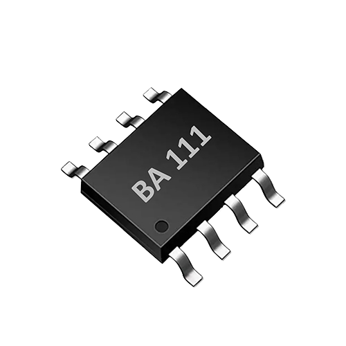
Household water purifiers usually need to measure two locations: the inlet (raw water) and the outlet (purified water), in order to calculate the desalination rate or display inlet and outlet TDS. This requires at least two TDS channels. If the product only displays outlet TDS or is only used for filter life reminders, a single channel may be sufficient. AtomBit offers the single-channel BA111 and the dual-channel BA112, corresponding to different requirements.
- Displaying only outlet TDS: the single-channel BA111 is sufficient.
- Displaying both inlet and outlet TDS, calculating removal rate, or requiring inlet temperature compensation: the dual-channel BA112 is more suitable.
2.2 Inlet and outlet probe positions and flow path design
Probe position directly affects reading response speed and accuracy. The inlet probe should be installed after pretreatment and before the RO membrane to avoid interference from large particulate impurities; the outlet probe should be installed on the RO membrane permeate side or after the post-carbon filter, close to the outlet. The flow path should avoid dead zones to ensure sufficient exchange as water flows over the probe surface. For compact water cups or pet water dispensers, the probe structure needs to be miniaturized, and anti-bubble design should be considered.
In smart water appliances and OEM integration, AtomBit can provide compact probes as well as customization of structure, wiring harness, interface and application calibration to help product teams adapt to different flow paths.
2.3 Range selection: the boundaries of household scenarios
Household tap water TDS is typically between 50–800 ppm, and may be higher in some regions. RO permeate TDS is generally below 50 ppm, or even below 10 ppm. Therefore, the 0–3000 ppm range (BA111) covers the vast majority of household scenarios; if high-hardness raw water needs to be handled or the sensor is used for other liquids (such as boiler water detection in coffee machines), the wide 0–10000 ppm range of BA112 provides greater margin. Note: a wider range does not mean higher accuracy; selection should be based on the actual water quality range to avoid over-design. For coffee machines, boiler water may increase in TDS due to concentration, and a wide range helps prevent over-range; for smart water cups, users may fill them with mineral water or electrolyte drinks, so the range also needs margin.
2.4 Probe: bipolar drive and structural adaptation
TDS measurement is essentially conductivity measurement, and DC drive causes electrode polarization, affecting long-term stability. Both BA111 and BA112 use bipolar drive; alternating polarity reduces probe polarization and extends probe life. Bipolar drive alternates the electrode polarity to avoid ion accumulation and electrode surface changes caused by current in a single direction, thereby maintaining measurement stability. Probe materials are usually stainless steel or graphite, selected according to liquid compatibility and cost. Structurally, probe spacing, surface area and insulation design affect the cell constant, and thus the measurement range and accuracy. Coaxial or parallel electrode designs need to match the flow path to avoid turbulence effects. Product teams should confirm with the probe supplier or AtomBit's OEM support team that the cell constant matches the ASIC's excitation parameters.
2.5 Temperature compensation must be built in
The conductivity of water changes significantly with temperature, by about 2% per degree Celsius. TDS readings without temperature compensation may differ by more than 20% between winter and summer. Both BA111 and BA112 integrate temperature measurement and TDS temperature correction, so compensation can be completed without an additional temperature sensor. For dual-channel designs, BA112 provides two temperature channels, which can separately compensate the temperature difference between inlet and outlet, improving the accuracy of removal rate calculation.
2.6 Power consumption and interfaces: UART and BURST modes
Smart small appliances are usually sensitive to power consumption, especially battery-powered smart water bottles or pet water dispensers. BA111 and BA112 are both controlled via UART commands, making integration with the host MCU easy. BA112 also supports automatic BURST mode: the ASIC can periodically sample and update data automatically, and the host reads it when needed, reducing host wake-up frequency and system power consumption. For battery-powered pet water dispensers or portable water bottles, BURST mode allows the ASIC to operate at a lower duty cycle, for example sampling once every 10 minutes and sleeping the rest of the time, with the host reading results only when the display needs updating. During design, evaluate the balance between sampling interval and power consumption: frequent sampling improves real-time performance but increases power consumption; BURST mode suits periodic reporting scenarios (such as updating filter status once per hour).
2.7 Calibration process: single-point or two-point
Calibration is key to ensuring product consistency. BA111 supports TDS temperature correction, but the calibration method is not detailed in the data; BA112 explicitly supports two-point calibration. Production calibration recommendations:
- Single-point calibration: calibrate at a fixed temperature using a standard conductivity solution (such as 1413 µS/cm or 1000 ppm NaCl equivalent), suitable for low-cost products with general accuracy requirements.
- Two-point calibration: perform linear calibration using two standard solutions of different concentrations (such as low concentration and high concentration), suitable for products requiring higher linearity; BA112 supports this method.
- Temperature calibration: verify the temperature channel in a constant-temperature bath to ensure correct compensation.
Calibration data can be stored in the MCU or inside the ASIC (if supported), and the production line writes calibration coefficients via UART commands.
3. Chip comparison: BA111 and BA112
| Feature | BA111 | BA112 |
|---|---|---|
| TDS measurement range | 0–3000 ppm | 0–10000 ppm |
| Number of channels | Single-channel TDS + temperature | Dual-channel TDS + dual temperature |
| Probe diagnostics | Not mentioned | Supports suspended probe and NTC open-circuit/short-circuit diagnostics |
| Drive method | Bipolar drive | Bipolar drive |
| Calibration | Temperature correction | Two-point calibration |
| Interface | UART | UART + automatic BURST mode |
| Application scenarios | Single-point outlet TDS display, simple filter indicator | Inlet/outlet comparison, removal rate calculation, wide range, diagnostic functions |
This table is based only on AtomBit public product information; refer to the latest datasheet for specific parameters.
4. Implementation steps
- Define product requirements : Is inlet/outlet TDS display required? Is removal rate calculation required? What is the display resolution? What is the power budget?
- Select the ASIC : choose BA111 or BA112 according to the number of channels and the measurement range.
- Design the probe and flow path : confirm the electrode constant, materials and structure with the probe supplier, and design the flow path to avoid dead zones and bubbles.
- Hardware integration : the ASIC peripheral circuit is extremely simple (both BA111/BA112 are described as "Minimal external circuitry"), requiring only a few resistors and capacitors and a UART connection.
- Firmware development : implement UART command parsing, data reading, temperature compensation calls and calibration coefficient storage.
- Calibration and validation : calibrate with standard solutions on the production line, and perform temperature cycling and long-term stability tests.
- Mass production validation : sample inspection for consistency, record calibration data, and establish a failure analysis process.
5. Limitations and boundaries
- TDS is not a specific indicator: it cannot distinguish beneficial minerals from harmful ions, and cannot indicate bacteria, viruses, heavy metals, pesticide residues, etc.
- Limited temperature compensation range: errors increase when outside the temperature range specified by the ASIC.
- Probe contamination and scaling: after long-term use, scaling on the electrode surface changes the cell constant, so the probe needs periodic cleaning or replacement.
- Flow channel and bubble effects: bubbles adhering to the probe cause low or fluctuating readings; venting should be considered in the design.
- Calibration drift: aging of electronic components and the probe may cause drift; it is recommended to define a calibration cycle for the product or use the diagnostic function (BA112) to indicate probe abnormalities.
6. Verification methods
- Standard solution verification: test with standard solutions of various known conductivities (e.g., 84 µS/cm, 1413 µS/cm, 12.88 mS/cm) at different temperatures and calculate the error.
- Temperature cycling test: measure the same solution at 5°C, 25°C and 45°C to verify temperature compensation.
- Long-term immersion test: immerse the probe in typical water quality for 30 days and monitor reading drift.
- Full inspection/sampling inspection on the production line: quickly verify each device with a standard solution and record the data for SPC.
- Fault injection test: for BA112, simulate probe disconnection or NTC short circuit to verify whether the diagnostic function is triggered.
7. FAQ
Q1: Is lower TDS water better? No. TDS only reflects the total amount of dissolved solids and cannot determine water safety. Low TDS in RO product water is normal, but mineral water may have a higher TDS and be beneficial.
Q2: Why is temperature compensation needed? Because conductivity changes with temperature, and without compensation the readings will have errors. BA111/BA112 integrates temperature measurement and correction, so no additional design is needed.
Q3: How to choose between BA111 and BA112? If you only need single-point outlet TDS display and the range is within 3000 ppm, BA111 is more economical; if you need dual channels for inlet and outlet water, a wide range, probe diagnostics or automatic BURST mode, choose BA112.
Q4: How often does the probe need to be replaced? It depends on water quality and frequency of use. It is generally recommended to check every 6–12 months, and replace it if readings are abnormal or drift significantly. The probe diagnostics of BA112 can assist in judgment.
Q5: How to reduce power consumption? Use the automatic BURST mode of BA112 to reduce the wake-up frequency of the main controller; or use BA111 and control the measurement timing through UART commands to avoid continuous measurement.
8. Conclusion
For household water purifier TDS detection solution selection, you should not only look at the chip unit price, but comprehensively consider display requirements, flow channel location, range, probe compatibility, temperature compensation, power consumption interface and calibration process. AtomBit BA111 and BA112 provide practical options from single-channel to dual-channel and from 3000 ppm to 10000 ppm, and simplify integration into smart small appliances through UART and BURST mode. Product teams should collaborate with probe and ASIC suppliers early in the design phase, clarify boundaries, and complete sufficient calibration and verification, so that TDS detection can truly become a reliable tool for improving user experience and filter management.