
Why you can't just read two TDS numbers
Household water purifier panels commonly show displays such as "raw water TDS 150, purified water TDS 10." If the raw water value is read before startup and the purified water value is read after water production is complete, subtracting the two does not represent the desalination capability of the device. The reason is that the flow rates at the two moments differ, the temperatures differ, the residual water conditions in the piping differ, and the probe surfaces may also be at different stages. Conductivity is significantly affected by temperature, typically about 2%/°C (varies by water sample), and readings at different temperatures cannot be directly compared.
Therefore, what the product side needs to do is not "read two numbers," but rather treat inlet and outlet as synchronized samples within the same steady-state water production cycle, and make clear that this data is used for device feedback, filter management, and trend indication, not for laboratory water quality determination.
First define the application boundaries
Built-in conductivity/TDS measurement belongs to consumer-grade screening, device feedback, and trend indication. Conductivity reflects the total amount of conductive ions in water, and TDS is usually converted from conductivity; the ionic composition differs among water sources, so the conversion factors are not entirely the same. Device-displayed values are not equivalent to laboratory gravimetric TDS, nor can they replace testing for specific contaminants such as microorganisms, organic matter, and heavy metals. The product UI, instructions, and promotional wording should all state that it is "used for operating status and filter trend management, and not as a criterion for direct drinking water safety."
Measurement point location and piping design
- Inlet measurement point: It is recommended to place it before the first-stage filter and after the pressure stabilizing valve or pressure reducing valve, avoiding the inlet solenoid valve, the booster pump inlet and outlet, and the vent, to reduce pulses and bubbles. It should preferably be set in a bypass or flow cell with stable flow velocity and no dead water zone.
- Outlet measurement point: Place it after the last-stage filter and before the water outlet. For storage-type systems, consider the TDS rise caused by the storage container and the post-filter; when sampling, first drain the residual water in the piping and wait for the flow to stabilize.
- Probe spacing and interference: Do not install the two probes close together, to avoid mutual electric field interference; the flow cell should have a venting structure, and the probe surface must not be covered by bubbles.
- Not recommended to use single-channel switching for comparison by default: If single-channel switching is used to reduce cost, the dead volume, delay, and cross-contamination caused by the switching valve must be evaluated. Using a dual-channel chip allows simultaneous acquisition at two measurement points, reducing time misalignment.
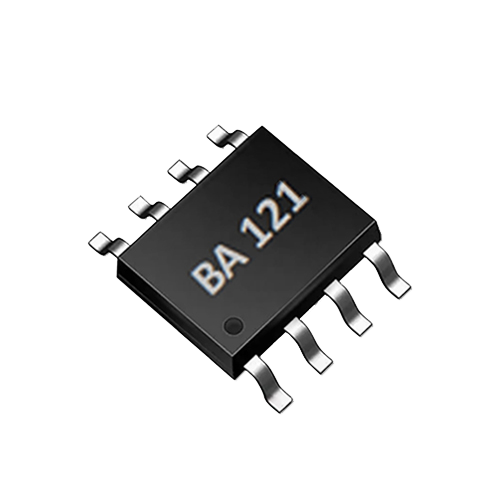
AtomBit BA022 integrates two 0–6000 µS/cm conductivity channels, suited to multi-point or comparative measurement in RO, hydrogen water and tap water equipment; BA121 is a single-channel conductivity and water temperature ASIC, suitable for compact single-point monitoring. For inlet/outlet comparison, prefer the dual-channel architecture.
Time synchronization and sampling window
Do not use the instantaneous point value at startup. It is recommended to collect a continuous window after the system reaches steady state: for example, sample once every 1 seconds for 10–20 seconds, and take the median or trimmed mean. This reduces the effects of bubbles, pressure fluctuations and probe response time.
BA022 is a compact reference design controlled by UART, making it easy for the host to pack the data of both channels into the same frame and add a timestamp, reducing the time offset between inlet and outlet measurements. If BA121 is used in the product for single-point monitoring, do not use it as a strict inlet/outlet comparison; single-point is more suitable for raw water anomaly alerts or outlet trends.
Temperature compensation and temperature synchronization
Conductivity measurement must include temperature compensation, typically normalized to 25°C. Inlet and outlet temperatures may differ: RO membrane operation, pump heating and ambient temperature can cause differences. The main pipe temperature cannot be used in place of the two measurement points.
BA022 provides automatic temperature correction from 0–100°C; during integration, it is recommended to place a temperature sensor close to each probe to reduce thermal lag and the effect of cable heat conduction. If the structure allows only one temperature sensor, confirm during product validation that the inlet/outlet temperature difference is within the target accuracy; measuring temperature separately on both channels is the more reliable approach.
Validation method: place the two channel probes separately in a constant-temperature water bath, apply temperature steps at 25°C, 35°C and 50°C, check whether the compensated readings are consistent, and record the response time.
Flow variation and probe installation
Conductivity measurement is sensitive to flow conditions: too low a flow may cause lag in ion transport, while too high a flow may generate bubbles or cause erosion. Water purifiers go through processes such as startup, steady state and storage pressure fluctuations.
Design recommendation: use the flow meter or pump status as the measurement trigger condition and only take stable flow windows. Without a flow meter, a rough judgment can be made based on pump duty cycle or pressure changes.
Probe installation should avoid horizontal tops where bubbles accumulate and bottoms where sediment collects; a full-pipe flow cell with a venting structure is recommended. BA022 uses bipolar probe drive to reduce polarization effects; however, bubbles, particulate contamination and scaling on the electrode surface still need to be addressed through water path and structural design. When inlet and outlet flows differ, do not share the same flow cell without adaptation; design separate flow restriction structures.
Data display and filter management
The product interface is recommended to display "inlet conductivity," "outlet conductivity," "rejection rate/desalination rate," and "measurement status" at the same time. The rejection rate can be used as a trend reference according to the following formula:
Rejection rate (%) = (1 - outlet conductivity / inlet conductivity) × 100%
Note: This value is meaningful only when collected at the same time and under the same temperature compensation conditions; when the raw water TDS is very low, the difference is small and the signal-to-noise ratio is low, so the rejection rate tends to jump, and a dead zone should be set or multiple water-production cycles should be used for judgment.
| Item | BA121 single channel | BA022 dual channel |
|---|---|---|
| Number of channels | 1-channel conductivity | 2-channel conductivity |
| Range | Single-channel conductivity detection, subject to the specification sheet | 0–6000 µS/cm/channel |
| Temperature correction | Automatic temperature correction | Automatic temperature correction, 0–100°C |
| Probe drive | Bipolar probe drive | Bipolar probe drive |
| Application scenarios | Compact single-point monitoring | Multi-point or comparative measurement for RO, hydrogen water, and tap water equipment |
Filter life cannot be judged by conductivity alone. Conductivity mainly indicates abnormal RO membrane salt rejection, seal leakage, changes in feed water salinity, and similar issues; it must also be combined with flow rate, water consumption, operating time, and other sensor signals. An alarm strategy can be set as follows: if the removal rate stays below a set value for several consecutive water-production cycles, trigger a filter or seal inspection; if feed water conductivity rises abnormally, indicate a pre-filter or water source change. Thresholds must be calibrated according to the water quality in the target region and the product definition.
Selection and integration steps
- Define sampling points: confirm the specific positions of the inlet and outlet in the water purifier's water path, and design venting and flow-stabilizing structures.
- Install probes and temperature sensors: measure temperature close to each measurement point to avoid bubbles and deposits.
- Circuit integration: use the BA022 dual-channel reference design, read both channels synchronously via UART, and add host timestamps.
- Calibration: use traceable standard conductivity solutions at at least two concentration points, and check linearity, repeatability, and temperature compensation.
- System joint debugging: simulate different feed water TDS, temperature, and flow on a constant-temperature water bath and an adjustable-flow test bench to verify synchronicity and removal rate calculation.
- Mass-production verification: sample multiple devices, record channel-to-channel deviation, temperature drift, long-term operation drift, and scaling, and add automatic cleaning or probe status monitoring if necessary.
Limitations and Validation Methods
Built-in household conductivity/TDS measurement is not selective analysis. It cannot identify specific heavy metal forms, microorganisms, organic pollutants, or colloids. Temperature compensation is an approximation method and is affected by water sample composition and probe surface condition; probe contamination, bubbles, and insufficient sample representativeness will all reduce data validity.
Verification methods should at least include: synchronous comparison with a laboratory conductivity meter, repeatability testing with standard solutions, consistency testing across multiple units, temperature cycling, and long-term aging with continuous water flow. Networked products can transmit inlet and outlet water trends back for filter life algorithms, but user privacy must be protected and trend data must not be interpreted as compliance testing.
Conclusion
To compare inlet and outlet conductivity in household water purifiers, a systematic engineering approach is needed across five aspects: measurement point location, time synchronization, temperature compensation, flow variation, probe installation and data presentation. The dual-channel chip BA022 can reduce the difficulty of synchronized measurement, but the complete appliance still needs to address water path, structure, calibration, algorithm and mass-production consistency issues. Only by making the measurement window stable and clearly defining the display basis can inlet and outlet conductivity data be truly useful to users and for filter management.
FAQ
Q1: Can I install just one conductivity sensor and switch it to measure inlet and outlet water? can be used for low-cost single-point inspection, but switching introduces time differences, dead volume and cross-contamination, so it is not suitable for near-real-time comparison. For rigorous inlet/outlet comparison, dual-channel simultaneous acquisition is recommended, for example BA022.
Q2: Does a large conductivity difference between inlet and outlet water mean the water purifier is definitely compliant? No. Conductivity only reflects total ionic strength and cannot cover risks such as microorganisms, organic matter and colloids, and it is affected by temperature, flow and water draw method. It is suitable as an indicator of equipment operation and filter trends, but cannot replace compliance or safety determinations.
Q3: How can I avoid TDS value jumps at the moment of startup? Wait until the water path flow is stable and residual water in the tubing has been flushed out before sampling, then use a moving average or take the median of a continuous window. The product interface should display a "stable value" or "measuring" status rather than an instantaneous fluctuating value.
Q4: Is it acceptable to use only one temperature sensor for temperature compensation? Not recommended. There may be a temperature difference between inlet and outlet water, especially in machines with a pump or during long operation. It is recommended to measure temperature separately at the two measurement points; BA022 provides automatic temperature correction from 0–100°C, but the temperature measurement points should still be close to their respective probes.
Q5: What should be done when the raw water TDS is very low and the removal rate fluctuates greatly? Because the difference is small and the signal-to-noise ratio is low, the instantaneous removal rate should not be used as the sole indicator. A dead zone can be set, trend judgment across multiple water-production cycles can be used, or absolute conductivity values can be displayed at the same time to prevent user misinterpretation.