
Introduction: TDS Integration Challenges in Small Water Devices
In products such as smart water bottles, pet water fountains, coffee machines, and countertop water dispensers, water-quality TDS detection is shifting from standalone benchtop meters to embedded functionality. Hardware teams face challenges: limited PCB area, compact structures, short probe cables, battery power, and fast assembly testing. Traditional discrete op-amp + ADC + MCU high-frequency excitation schemes not only consume large board space but also introduce polarization, noise, and consistency variations.
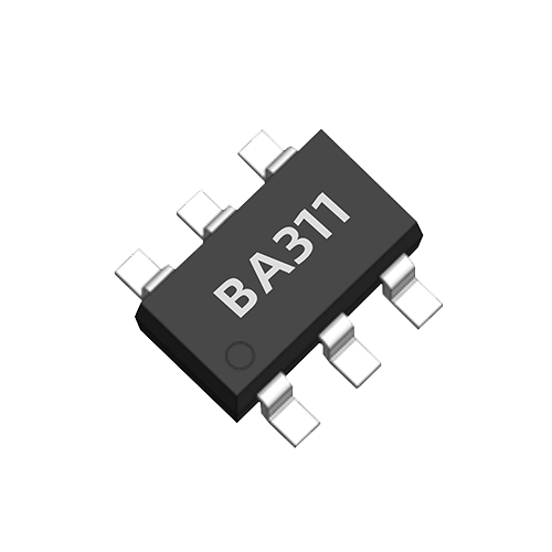
The AtomBit BA311 is a miniature TDS sensor interface ASIC designed for space-constrained smart water products, packaged in SOT23-6, with internal automatic measurement and data output. This article discusses integration methods based only on publicly available product facts: 0–3000 ppm TDS measurement, automatic 300 ms measurement cycle, 3–5 V wide-voltage supply, bipolar drive to reduce probe polarization, and BURST Tx data output. Applicable boundaries and undisclosed parameters are explicitly noted.
Scope and Fact Boundaries
The BA311 targets consumer-grade screening, equipment feedback, and trend indication in smart water appliances, such as:
- Inlet/outlet TDS comparison for home water purifiers and filter-life reminders.
- Water-quality/mineral reminders for countertop water dispensers and coffee machines.
- TDS recording and reminders for smart water bottles and pet water fountains.
- TDS probe front-ends for small OEM modules.
It does not replace laboratory conductivity meters or compliance testing. The database specifies a range of 0–3000 ppm; therefore, scenarios beyond this range, high-salinity, or industrial wastewater are outside the default scope. Public documents do not mention temperature compensation, accuracy specifications, probe-constant adaptation algorithms, or BURST frame format details; integration requires obtaining the datasheet or application notes from AtomBit and validating through testing.
1. PCB Space and Layout
The SOT23-6 package itself occupies approximately 3 mm × 3 mm (including pins), which is friendly for 4-layer or 2-layer small boards. However, a small package does not mean arbitrary layout.
Layout recommendations:
- Keep analog inputs short. Probe excitation/sampling pins to the probe connector or pads should be short and direct, avoiding parallel routing with switching power supplies, display backlights, or Wi-Fi/Bluetooth RF traces.
- Place power decoupling near the chip. Within the 3–5 V range, typically place a 100 nF capacitor near the power pin; if power fluctuation is significant, add a 1 µF storage capacitor. Exact values per the datasheet.
- Use single-point grounding and ground planes. TDS measurement is essentially a high-impedance/low-current signal; ground bounce can directly affect readings. Avoid mixing the probe return path with power ground.
- Ensure data output lines do not cross high-current loops. If the MCU is on another board or at a distance, add a small series resistor or RC filter, but do not slow the rising edge too much to affect reception.
- Reserve test points. At least keep test points for power, ground, probe input, and data output to facilitate production ICT/FCT and failure analysis.
If the product places the BA311 on a small board at the probe tail, pay more attention to connector insertion stress and cable twist to avoid stress on SOT23-6 solder joints.
2. Interface and Data Link
The BA311's BURST Tx data output reduces MCU analog front-end requirements; the MCU does not need a high-accuracy ADC, only a digital input to parse data. However, integration cannot assume "plug-and-play."
Points to confirm and verify:
- Whether high/low levels match the MCU power domain; under 3–5 V supply, output high is typically near VDD; if the MCU is 1.8 V domain, level shifting or voltage division is needed.
- Whether the data output is open-drain/push-pull and whether it has an internal pull-up determines if an external pull-up resistor is required.
- Time interval and frame length: The automatic 300 ms measurement cycle is given, but specific bit definitions, rate, and start/stop conditions within the data frame must be per the datasheet.
- The delay from power-up to the first valid data frame and interval jitter in continuous output should be confirmed with a logic analyzer.
- On the MCU side, validate after receiving a complete frame, discard incomplete or abnormal frames, and apply a sliding average over multiple consecutive reads.
Firmware flow reference: wait for stabilization after startup, enable/read data, receive complete frame, convert to ppm via lookup table/formula, apply filtering and threshold judgment, report or drive indicators. For low real-time requirements, the 300 ms automatic cycle can be used for timestamped recording, which is better than the MCU blindly sampling continuously.
3. Probe Matching and Bipolar Drive
TDS measurement relies on electrode probes. The BA311's bipolar drive reduces probe polarization, which is especially important for long-term immersion or frequent measurement scenarios. However, "reduced polarization" does not mean "any probe works universally."
Integration highlights:
- The cell constant must match the input range. 0–3000 ppm typically corresponds to tap water, drinking water, and some filtered water; however, if the cell constant is too high or too low, it may exceed the chip's effective signal range. After selection, validate with standard solutions.
- Probe material: Stainless steel, titanium, graphite, or platinum-plated electrodes differ in durability, polarization, and contamination. Bipolar drive can mitigate polarization but cannot completely eliminate scaling or bubble effects on the surface.
- Structurally, avoid trapping bubbles near the probe; install in flowing water or a fully wetted area; an inclined position or near the outlet is more stable than a top blind pipe.
- Cables: Keep the distance from probe to BA311 as short as possible; if extended, use shielded cables with single-point grounding of the shield to avoid antenna effects.
No probe constant adaptation range or automatic temperature compensation is provided for the BA311; therefore, the same firmware mapping table may require recalibration for different probes/water temperatures. Do not directly map a probe reading fixedly to ppm; instead, perform product-level calibration.
4. Power Consumption and Power Strategy
The 3–5 V wide supply allows the BA311 to be used in lithium battery, USB, or 3.3 V/5 V systems. The automatic 300 ms measurement cycle means it is not continuous high-frequency measurement, suitable for intermittent water-quality detection.
However, power design requires measurement:
- Public documents do not provide operating current, standby current, or shutdown mode; do not assume "ultra-low power."
- If the system does not need detection most of the time, the MCU can control the BA311 power on/off, or use system power management periodic wake-up. This assumes confirmation that the chip can output valid data within the expected time after power-up and that frequent power cycling does not affect measurement stability.
- For battery products, measure the average current, peak current, and power-on surge under the 300 ms cycle, then decide whether current limiting, soft start, or an independent LDO is needed.
Engineering-wise, design can be: measure once per day/hour, read 2–3 valid frames each time and average, then power down the front-end. This satisfies water-quality trend recording while controlling power. However, firmware must handle power-up stabilization and probe wetting/bubble release time.
5. Structure and Assembly Testing
The SOT23-6 small package is suitable for integration with probes and connectors into a compact module or directly mounted at the edge of the main control board. Structural and process notes:
- Pad design: SOT23-6 pad pitch is small; control reflow soldering process window to avoid solder bridging or cold joints. For small-batch prototypes, recommend AOI inspection.
- Waterproofing and condensation: Internal humidity in water devices is high; PCBA needs conformal coating or localized potting, but avoid probe input and high-impedance nodes to prevent leakage causing TDS drift.
- Potting: If the entire module is potted, the potting compound may seep into the probe electrodes or alter the electrode surface; verify reading consistency before and after potting.
- Assembly positioning: The relative position of the probe and water flow channel affects measurement stability more than the chip itself; fix the probe to avoid vibration or water hammer causing changes in electrode distance/contact.
- Production testing: Establish standard TDS test solutions (e.g., NaCl solution) and a reference meter comparison station; test at least low, medium, and high concentration points per board, record deviation and repeatability; for out-of-tolerance boards, troubleshoot soldering, probe incoming quality, and contamination.
6. Selection Decision and Alternatives
Before choosing the BA311, consider the following questions:
- Is the product's maximum TDS within 0–3000 ppm? If it is just purifier outlet or water dispenser tank, basically yes; if it is seawater, concentrated water, or high-hardness raw water, it may exceed.
- Is multi-parameter measurement needed? The BA311 only provides TDS interface, not temperature, pH, turbidity, etc. If multi-spectral or micro-optical sensing is needed, evaluate other AtomBit optical solutions, but do not strongly couple them in the same chain.
- Does the measurement cadence match the 300 ms automatic cycle? If it is just trend and filter reminder, sufficient; if fast transient or high-speed sampling is required, evaluate.
- Is SOT23-6 strictly required for shape and volume? If it is an extremely small module, the BA311 has advantages; if board area is not sensitive, discrete solutions are possible, but consistency may be inferior to the ASIC.
- Do firmware resources support parsing BURST Tx? Without a logic analyzer and protocol documentation, development risk increases; obtain support in advance.
If the above conditions are met, the BA311 can be integrated as a front-end ASIC; if not, contact AtomBit for customized probes, interface chips, or OEM/ODM evaluation. The database shows AtomBit provides interface chips, compact probes, and customization of structure, cables, interfaces, and application calibration in smart water appliances and OEM integration, consistent with the BA311 integration path.
7. Verification Methods
Recommend verification at the following levels:
| Verification Level | Method | Key Metrics |
|---|---|---|
| Single Board | Simulate the probe with standard resistors/standard conductivity and check output frames and repeatability | Reading stability, frame error rate, power-on delay |
| Probe Level | Compare probes with different constants in 300/1000/2000 ppm standard solutions | Linearity, deviation, polarization recovery |
| Full System | Long-term recording under actual water flow, temperature, bubbles, and vibration | Drift, jumps, water hammer effects |
| Production Line | Fast testing at low/medium/high concentrations, compared with reference meter | Consistency, CPK, rework rate |
For standard solutions, use NaCl or KCl solutions prepared with a calibrated conductivity meter; note the temperature effect on conductivity and record water temperature during testing. Do not use tap water or mineral water as the sole standard.
FAQ
Q1: Which products is the BA311 suitable for? It is suitable for space-constrained smart water appliances within the 0–3000 ppm range, such as water dispensers, water purifier reminders, coffee machines, smart water cups, and pet water fountains. It is not suitable for compliance testing or industrial wastewater.
Q2: Can the BA311 measure above 3000 ppm? Based on publicly available data, the range is 0–3000 ppm. Accuracy or linearity cannot be guaranteed beyond this range; other sensors or solutions should be considered.
Q3: Is it complicated to interface with an MCU? The BA311 outputs BURST Tx data, and the MCU needs to parse the digital frames. Levels, timing, and frame format must be implemented according to the datasheet; it is recommended to verify with a logic analyzer.
Q4: What is the significance of the automatic 300 ms measurement cycle? It indicates that the chip can automatically output measurement results at approximately 300 ms intervals, which is suitable for intermittent reading and trend recording, reducing the continuous sampling burden on the MCU. Specific power-on to valid output still needs testing.
Q5: Is temperature compensation required? The publicly available documentation does not list a temperature compensation feature. TDS readings are affected by temperature. If the product operates in a wide temperature range, external temperature compensation should be evaluated, or contact AtomBit for temperature characteristics.
Q6: How can probe polarization be avoided? The BA311 uses bipolar driving to reduce probe polarization, but electrode material, avoiding prolonged DC immersion and bubble adhesion, and verifying long-term stability in full-machine testing are still necessary.
Conclusion
The value of the BA311 lies in compressing the automatic TDS measurement chain into an SOT23-6 package, simplifying the analog front end for small water devices. However, microchip integration does not mean "no design"; true stability comes from probe matching, layout, firmware parsing, and full-machine calibration. As long as the applicable boundaries and unspecified parameters are clearly understood, the BA311 can serve as a reliable and space-saving TDS interface solution for smart water appliances.