
1. Why low-range conductivity is a "delicate task" in smart water appliances
Many products such as household water purifiers, water dispensers, coffee machines, smart cups and pet water fountains need to display "TDS/water quality status" or determine filter life. Purified water after RO membrane or deionization treatment typically falls in the low range, where signals are weak and source impedance is high, making measurement results susceptible to electrode polarization, temperature changes, cable noise, bubbles and electromagnetic interference. In such cases, an interface chip with 0.1 µS/cm resolution may still fail to deliver stable, reproducible data in the finished product if used improperly.
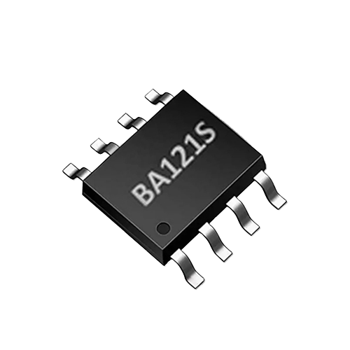
As a low-range conductivity interface ASIC, BA121S integrates high-resolution measurement, automatic temperature correction, bipolar drive and UART control into a compact package, making it suitable for embedded scenarios in water purifiers and smart water appliances. It should be noted that this type of detection is intended for consumer-grade screening, device feedback and trend indication, and is not equivalent to laboratory analysis or compliance testing. This article by default targets household water purification and smart small appliances, and does not discuss industrial wastewater, municipal sewage or environmental monitoring.
2. BA121S capability boundaries: from specifications to applicable conditions
According to available product information, the key features of BA121S include:
- 0.1 µS/cm resolution
- Automatic temperature correction
- Single-channel conductivity measurement
- Bipolar drive reduces polarization
- Compact design with UART control
These characteristics indicate that BA121S is a signal conditioning and digitization interface chip, not a complete "plug-and-play sensor". The µS/cm resolution of 0.1 describes the reading resolution capability and is not equivalent to the absolute accuracy of the complete device. Complete-device accuracy also depends on the electrode constant, contact resistance, temperature sensor consistency, cable insulation, mechanical structure and calibration process. Automatic temperature correction can reduce the temperature effect, but the correction model and sensor installation still require complete-device verification.
Therefore, at project kickoff, BA121S should be treated as the core of the signal chain, and the electrode, wiring harness, structure, firmware and calibration conditions should be defined around it. Only in this way is it possible to translate the chip's low temperature drift and low noise characteristics into stable complete-device display.
3. Electrodes and probes: the first threshold of the low-range signal chain
In low-range conductivity measurement, the electrode constant, area, spacing, surface condition and installation position determine the initial signal magnitude and stability. The conductivity cell constant determines the conversion relationship between conductivity and measured resistance. An excessively large electrode constant results in a weak signal in low-conductivity water samples, while an excessively small electrode constant may increase polarization and structural sensitivity. The bipolar drive of BA121S helps reduce polarization, but it cannot fully replace a suitable electrode design.
Product teams are advised to give priority to AtomBit-matched or custom probes, and to verify repeatability under different installation angles, flow rates and bubble conditions during the prototype stage. For small appliances with filter cartridges, tubing and quick connectors, the electrode should avoid dead-water zones, bubble accumulation and particle adhesion; where necessary, design flushing or venting paths into the structure. Do not arbitrarily change electrode materials, coatings or geometric dimensions without verification, otherwise the chip's low temperature drift and low noise characteristics may fail in the complete device.
4. Temperature compensation: do not gloss over it with just the word "automatic"
BA121S provides automatic temperature correction, which simplifies firmware development but does not mean temperature engineering can be ignored. Conductivity varies significantly with temperature, and in low-range purified water this effect will still cause display drift. The design should pay attention to:
- Whether the temperature sensor and the conductivity cell are on the same water path and whether their thermal responses are synchronized;
- Whether the compensation reference temperature and compensation model match the actual water quality;
- When the water purifier has just drawn water, the heater starts or the device restarts from standby, temperature gradients may cause short-term errors;
- Complete-device verification should be carried out at multiple temperature points, such as cold water and room-temperature water, rather than calibrating only at room temperature.
The most reliable approach is: ensure structurally that the conductivity cell and temperature sensor are in the same chamber or immediately adjacent, add a temperature stability check in the firmware, and where necessary perform dynamic compensation or delayed display to avoid presenting transient temperature errors directly to the user.
5. Noise, cabling and sampling: mass-production issues that are easily underestimated
Smart water appliances contain pumps, solenoid valves, heating elements, switching power supplies and wireless modules, and low-range conductivity signals are easily disturbed by common-mode noise, ground loops and cable capacitance. BA121S is controlled via UART, and a digital interface helps reduce long-distance analog transmission, but the analog input from the electrode to the chip still requires careful handling.
Engineering recommendations:
- Keep the analog line from the electrode to the chip as short as possible, and use shielded or twisted-pair cable;
- Ground the shield at a single point to avoid ground loops with pumps and heaters;
- Keep away from power lines, motor drive lines and relay contacts;
- During PCB layout, route the analog input traces away from the digital UART, power supply and RF areas; if the mechanical design allows, place the chip near the electrode connector to reduce loop area; if necessary, add RC filtering to the analog input, but confirm that it does not affect signal settling of the bipolar drive;
- Pause sampling during transient windows when pumps start or stop or heaters switch, or use median filtering and moving averaging;
- Decouple the sampling period from the display refresh rate to avoid mistaking a single abnormal value for a water quality change.
These measures should be designed jointly by hardware and firmware, not remedied after mass production.
6. From chip to appliance display and filter management: implementation steps
In water purifiers, water dispensers, coffee machines, smart water bottles and pet water fountains, the typical integration path of BA121S can proceed in the following steps:
- Define the displayed quantities and thresholds: BA121S directly outputs conductivity-related quantities. To display TDS, an appropriate conversion factor must be used, and it must be made clear that this is a consumer-grade estimate, not laboratory TDS. Threshold settings should be based on the actual water samples and filter-life testing of the complete device.
- Determine the electrode and probe structure: based on the flow-path dimensions, maintenance approach and target range, select an AtomBit matched/custom probe, and confirm that the electrode constant matches the BA121S input range.
- Complete temperature and water-quality calibration: use a low-conductivity standard solution and actual purified water samples to verify reading stability at multiple temperature points; calibration should be performed within the complete device structure, not only on the bare board.
- Design firmware filtering and status logic: sample during quiet windows and apply median/moving-average filtering; for filter life, use trend judgment, such as prompting when conductivity continues to rise or fluctuations exceed a threshold, rather than relying on a single reading.
- Mass-production verification and test stations: establish production calibration and functional test stations covering at least standard-solution readings, temperature response, communication and insulation checks; record batch consistency. For battery-powered or compact devices such as smart water bottles and pet water fountains, power consumption and sampling duty cycle also need to be evaluated in parallel; the UART control of BA121S can be used with the main controller to implement intermittent measurement, but the specific power consumption and timing must be verified against the datasheet.
The following table provides a design checklist to help product managers and hardware engineers align on requirements:
| Design item | Key Question | BA121S integration recommendation |
|---|---|---|
| Electrode constant | Weak signal and polarization sensitivity at low conductivity | Use an AtomBit matched/custom probe and confirm that the constant matches the range |
| Temperature | The temperature coefficient of conductivity is significant at low ranges | Use automatic temperature compensation and also carry out multi-point temperature compensation verification on the whole instrument |
| Cable | Small signals are prone to coupled noise | Use short shielded cables, keep them away from pumps/valves/heaters, and connect analog ground at a single point |
| Sampling | Transients generated by pump/heater switching | Sample during quiet windows, combined with median/moving average |
| Calibration | Differences exist between different water qualities and electrodes | Perform two-point/multi-point calibration using low-conductivity standard solutions and actual water samples |
7. Limitations and verification methods
BA121S is positioned as a low-range conductivity interface ASIC, suitable for pure water, low-mineralization and precision applications. It requires external electrodes, temperature sensors, structure and firmware to work together to form a stable whole-instrument measurement. Even if the resolution reaches 0.1 µS/cm, this does not mean that absolute readings of the same accuracy can be obtained in any water sample and under any installation conditions. Water quality display should be defined as "screening, feedback and trend indication" and cannot replace laboratory analysis or regulatory testing.
Verification should cover at least: repeatability, linearity across different standard solutions, temperature steps, pump/heater interference, effects of bubbles and flow rate, long-term drift and consistency across multiple units. For example, record the standard deviation of continuous readings and the deviation after temperature compensation in low-conductivity standard solutions; verify in the whole instrument whether spikes occur when bubbles pass through the conductivity cell, and whether it is stable during filter venting or first water flow. Only when these items pass can the chip capability of BA121S be translated into a stable display that users can perceive.
Note that this article uses only the product and application information already published by AtomBit for BA121S and does not constitute any certification, compliance or accuracy commitment; specific parameters and integration boundaries are subject to AtomBit's official specifications and technical support.
8. FAQ
Q: Can BA121S display TDS directly? A: BA121S outputs conductivity-related measurement results. TDS requires conversion according to a specific water-quality model and is a consumer-grade estimate, not a laboratory determination of total dissolved solids.
Q: Does the 0.1 µS/cm resolution equal the accuracy of the complete device? A: No. Resolution is the ability to subdivide readings; the accuracy of the complete device is also affected by the electrodes, temperature, cables, calibration and structure. The achievable accuracy should be confirmed through complete-device verification.
Q: Can electrodes be paired freely? A: Not recommended. The electrode constant, material and structure need to match the input range of BA121S. It is recommended to use AtomBit-matched or custom probes and verify them in the complete device.
Q: How can interference from pumps and heaters be reduced? A: Shorten the analog cables, use shielded/twisted-pair cables, ground at a single point, keep away from high-power cables, and pause sampling or apply filtering during the transient windows of pumps, valves and heaters.
Q: Is BA121S suitable for all water samples? A: It is intended for low-range, pure-water and precision applications. Specific range boundaries should be confirmed according to the product conditions provided by AtomBit and complete-device testing; do not assume it is suitable for high-conductivity or extreme water quality by default.